INSTALLATION
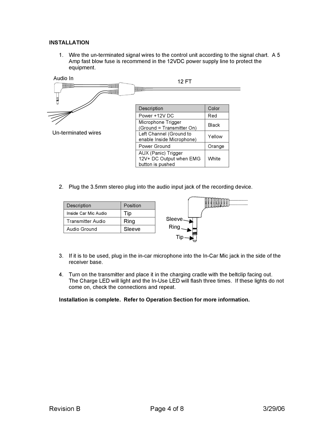
1.Wire the
Audio In |
|
|
| 12 FT |
|
|
|
| ||
|
|
|
|
|
|
|
|
|
| |
|
|
|
|
|
|
|
|
|
|
|
|
|
|
|
|
|
|
|
|
|
|
|
|
|
|
|
|
|
|
|
|
|
|
|
|
|
|
|
|
|
|
| |
|
|
|
|
|
|
|
|
|
|
|
|
|
|
|
| Description |
|
| Color |
| |
|
|
|
|
| Power +12V DC |
| Red |
| ||
|
|
|
|
| Microphone Trigger |
|
| Black |
| |
|
|
|
|
| (Ground = Transmitter On) |
|
|
| ||
|
|
|
|
|
|
| ||||
|
| Left Channel (Ground to |
|
| Yellow |
| ||||
|
|
|
|
| enable Inside Microphone) |
|
|
| ||
|
|
|
|
|
|
|
|
| ||
|
|
|
|
| Power Ground |
| Orange |
| ||
|
|
|
|
| AUX (Panic) Trigger |
|
|
|
| |
|
|
|
|
| 12V+ DC Output when EMG |
|
| White |
| |
|
|
|
|
| button is pushed |
|
|
|
| |
2. Plug the 3.5mm stereo plug into the audio input jack of the recording device.
Description | Position |
Inside Car Mic Audio | Tip |
Transmitter Audio | Ring |
Audio Ground | Sleeve |
Sleeve ![]() Ring
Ring
Tip ![]()
3.If it is to be used, plug in the
4.Turn on the transmitter and place it in the charging cradle with the beltclip facing out. The Charge LED will light and the
Installation is complete. Refer to Operation Section for more information.
Revision B | Page 4 of 8 | 3/29/06 |