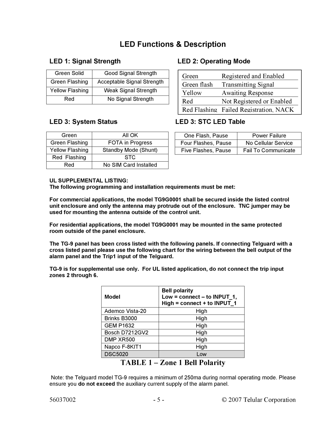
TG-9 specifications
The Telular TG-9 is a cutting-edge communication device that caters to various sectors, including remote monitoring, telematics, and industrial automation. Designed for versatility, the TG-9 excels in providing reliable connectivity while ensuring ease of integration into numerous applications.One of the key features of the Telular TG-9 is its robust GSM (Global System for Mobile Communications) compatibility. Utilizing GSM technology allows the TG-9 to leverage existing cellular networks, granting users the flexibility to deploy the device in areas lacking traditional wired infrastructure. This enhances mobility and accessibility, making it a preferred choice for businesses seeking real-time data transmission and remote access capabilities.
Another standout characteristic is the device's dual-band support, operating on both 850 MHz and 1900 MHz frequencies. This feature ensures optimal network coverage and reliability, enabling uninterrupted communication in diverse environments. The device is engineered to perform consistently, whether in urban centers or rural landscapes, making it suitable for various industries such as agriculture, logistics, and utilities.
The Telular TG-9 is also equipped with advanced power management technologies, allowing it to efficiently manage energy consumption. This is particularly beneficial for applications powered by battery sources, extending the operational life and reducing maintenance costs. Furthermore, the device supports a wide temperature range, ensuring performance in extreme weather conditions, which is vital for outdoor deployments.
Integration capabilities are another key feature of the TG-9. It supports a range of communication protocols, facilitating seamless connectivity with existing systems. This ease of integration allows for adaptability in deploying various applications, from asset tracking and fleet management to remote environmental monitoring.
Security is a paramount consideration in the design of the TG-9. The device includes features to safeguard data transmission, crucial for industries that handle sensitive information. With built-in encryption and secure connectivity options, the TG-9 provides peace of mind to users who prioritize data integrity.
In summary, the Telular TG-9 stands out with its GSM compatibility, dual-band operation, advanced power management, and robust security features. With its adaptability and reliability, the TG-9 is an ideal solution for businesses looking to harness the power of remote communication technology to optimize operations and enhance decision-making processes.
