Jumpers and Test Points
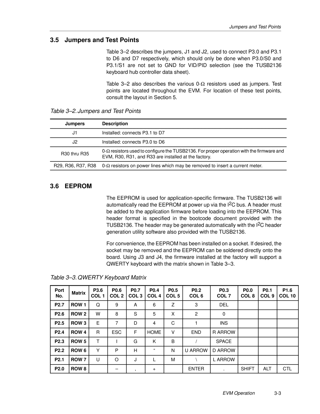
3.5 Jumpers and Test Points
Table
Table
Table 3–2. Jumpers and Test Points
Jumpers | Description | |
|
| |
J1 | Installed: connects P3.1 to D7 | |
|
| |
J2 | Installed: connects P3.0 to D6 | |
|
| |
R30 thru R35 | ||
EVM, R30, R31, and R33 are installed at the factory. | ||
| ||
|
| |
R29, R36, R37, R38 | ||
|
|
3.6 | EEPROM |
|
|
|
|
|
|
|
|
|
|
| ||
|
|
|
| The EEPROM is used for | ||||||||||
|
|
|
| automatically read the EEPROM at power up via the I2C bus. A header must | ||||||||||
|
|
|
| be added to the application firmware before loading into the EEPROM. This | ||||||||||
|
|
|
| header format is specified in the bootcode document provided with the | ||||||||||
|
|
|
| TUSB2136. The header may be generated automatically with the I2C header | ||||||||||
|
|
|
| generation utility software also provided with the TUSB2136. |
|
| ||||||||
|
|
|
| For convenience, the EEPROM has been installed on a socket. If desired, the | ||||||||||
|
|
|
| socket may be removed and the EEPROM can be soldered directly onto the | ||||||||||
|
|
|
| board. Using J3 and J4, the firmware installed at the factory will support a | ||||||||||
|
|
|
| QWERTY keyboard with the matrix shown in Table |
|
|
| |||||||
Table |
|
|
|
|
|
|
| |||||||
|
|
|
|
|
|
|
|
|
|
|
|
|
|
|
Port |
| Matrix | P3.6 |
| P0.6 | P0.7 |
| P0.4 | P0.5 | P0.2 | P0.3 | P0.0 | P0.1 | P1.6 |
No. |
| COL 1 |
| COL 2 | COL 3 |
| COL 4 | COL 5 | COL 6 | COL 7 | COL 8 | COL 9 | COL 10 | |
|
|
|
| |||||||||||
|
|
|
|
|
|
|
|
|
|
|
|
|
|
|
P2.7 |
| ROW 1 | Q |
| 9 | A |
| 6 | Z | 3 | DEL |
|
|
|
|
|
|
|
|
|
|
|
|
|
|
|
|
|
|
P2.6 |
| ROW 2 | W |
| 8 | S |
| 5 | X | 2 | 0 |
|
|
|
|
|
|
|
|
|
|
|
|
|
|
|
|
|
|
P2.5 |
| ROW 3 | E |
| 7 | D |
| 4 | C | 1 | INS |
|
|
|
|
|
|
|
|
|
|
|
|
|
|
|
|
|
|
P2.4 |
| ROW 4 | R |
| ESC | F |
| HOME | V | END | R ARROW |
|
|
|
|
|
|
|
|
|
|
|
|
|
|
|
|
|
|
P2.3 |
| ROW 5 | T |
| I | G |
| K | B | / | SPACE |
|
|
|
|
|
|
|
|
|
|
|
|
|
|
|
|
|
|
P2.2 |
| ROW 6 | Y |
| P | H |
| “ | N | U ARROW | D ARROW |
|
|
|
|
|
|
|
|
|
|
|
|
|
|
|
|
|
|
P2.1 |
| ROW 7 | U |
| O | J |
| L | M | \ | L ARROW |
|
|
|
|
|
|
|
|
|
|
|
|
|
|
|
|
|
|
P2.0 |
| ROW 8 |
|
| – | , |
| + |
| ENTER | . | SHIFT | ALT | CTL |
|
|
|
|
|
|
|
|
|
|
|
|
|
|
|
EVM Operation |