Manuals
/
Texas Instruments
/
Computer Equipment
/
Network Card
Texas Instruments
UCC38500EVM
manual
Operating Guidelines, Load Connections, Applying Input Power
Models:
UCC38500EVM
1
9
16
16
Download
16 pages
43.83 Kb
6
7
8
9
10
11
12
13
Power Management Products
Features
Using the UCC38500EVM
Page 9
Image 9
Page 8
Page 10
Page 9
Image 9
Page 8
Page 10
Contents
Using the UCC38500EVM
User’s Guide
SLUU068C
Power Management Products
Using the UCC38500
User’s Guide
February
IMPORTANT NOTICE
EVM IMPORTANT NOTICE
EVM WARNINGS AND RESTRICTIONS
1−1. DM38500 Evaluation Module Application Schematic
Contents
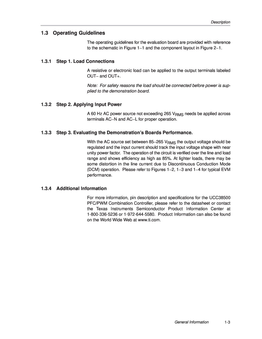
1.3.3 Step 3. Evaluating the Demonstration’s Boards Performance
1.3.4 Additional Information 1.4 DM38500 EVM Performance
Chapter
General Information
Page
Topic
J Controls Boost Preregulator to Near-unity Power Factor
1.1 Features
J Accurate Power Limiting J Improved Feedforward Line Regulation
1.2 Description
1.3 Operating Guidelines
1.3.2 Step 2. Applying Input Power
1.3.1 Step 1. Load Connections
1.3.3 Step 3. Evaluating the Demonstration’s Boards Performance
High-Voltage component. See
High-Temperature component
See EVM Warnings
EVM Warnings and
Figure 1−3. DM38500 Power Factor
1.4 DM38500 EVM Performance
Figure 1−2. DM38500 EVM Efficiency
Distortion
Figure 1−4. DM38500 Total Harmonic Distortion
Total
V IN = 265
Reference
DM38500 EVM Part Descriptions
DM38500 Board Layouts
Table 2−1. DM38500 Part Descriptions
2.1 DM38500 EVM Part Descriptions
3 Capacitor C38 is located at reference designator R38 on the PCB
2 Unless otherwise specified, all resistors have a tolerance of ±1%
Description
Value/Type Number
2.2 DM38500 Board Layouts
Figure 2−1. DM38500 EVM PC Board Top Assembly
Top
Page
Image
Contents