Installation Procedure ___________________________________________________

To assure maximum performance from your 800S series sprinklers, read these instructions completely prior to installation or service.

Constructing Swing Joints

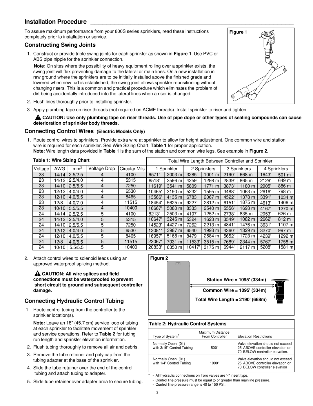
1.Construct or provide triple swing joints for each sprinkler as shown in Figure 1. Use PVC or ABS pipe nipple for the sprinkler connection.

Note: On sites where the possibility of heavy equipment rolling over a sprinkler exists, the swing joint will flex preventing damage to the lateral or main lines. On a new installation in raw ground where the sprinklers are to be initially installed above the finished grade and lowered when new turf is established, the swing joint allows sprinkler repositioning without changing risers. This is a common and practical procedure which eliminates the problem of dirt being accidentally introduced into the lateral lines when a riser is changed.

2.Flush lines thoroughly prior to installing sprinkler.

Figure 1

3. Apply plumbing tape on riser threads (not required on ACME threads). Install sprinkler to riser and tighten.

CAUTION: Use only plumbing tape on riser threads. Use of pipe dope or other types of sealing compounds can cause deterioration of sprinkler body threads.

Connecting Control Wires (Electric Models Only)

1.Route control wires to sprinklers. Provide extra wire at sprinkler to allow for height adjustment. One common wire and station wire is required for each sprinkler. See Wire Sizing Chart, Table 1 for proper application.

Note: Wire length data provided in Table 1 is the sum of the station and common wire legs. See example in Figure 2.

Table 1: Wire Sizing Chart


Total Wire Length Between Controller and Sprinkler


Voltage

AWG

mm2

Voltage Drop

Circular Mils

1 Sprinkler

2 Sprinklers

3 Sprinklers

4 Sprinklers

23

14/14

2.5/2.5

4

4100

6571'

2003 m

3285'

1001 m

2190'

668 m

1643'

501 m

23

14/12

2.5/4.0

4

5315

8518'

2596 m

4259'

1298 m

2839'

865 m

2129'

649 m

23

14/10

2.5/5.5

4

7250

11619'

3541 m

5809'

1771 m

3873'

1180 m

2905'

886 m

23

12/12

4.0/4.0

4

6530

10465'

3190 m

5232'

1595 m

3488'

1063 m

2616'

798 m

23

12/10

4.0/5.5

4

8465

13566'

4135 m

6783'

2067 m

4522'

1378 m

3391'

1034 m

23

12/8

4.0/7.0

4

11515

18454'

5625 m

9227'

2812 m

6151'

1875 m

4613'

1406 m

23

10/10

5.5/5.5

4

10400

16667'

5080 m

8333'

2540 m

5556'

1693 m

4167'

1270 m

24

14/14

2.5/2.5

5

4100

8213'

2503 m

4107'

1252 m

2738'

835 m

2053'

626 m

24

14/12

2.5/4.0

5

5315

10647'

3245 m

5324'

1623 m

3549'

1082 m

2662'

812 m

24

14/10

2.5/5.5

5

7250

14523'

4427 m

7262'

2213 m

4841'

1476 m

3631'

1107 m

24

12/12

4.0/4.0

5

6530

13081'

3987 m

6540'

1993 m

4360'

1329 m

3270'

997 m

24

12/10

4.0/5.5

5

8465

16957'

5168 m

8479'

2584 m

5652'

1723 m

4239'

1292 m

24

12/8

4.0/5.5

5

11515

23067'

7031 m

11533'

3515 m

7689'

2344 m

5767'

1758 m

24

10/10

5.5/5.5

5

10400

20833'

6350 m

10417'

3175 m

6944'

2117 m

5208'

1581 m

2.Attach control wires to solenoid leads using an approved waterproof splicing method.

CAUTION: All wire splices and field connections must be waterproofed to prevent short circuit to ground and subsequent controller damage.

Connecting Hydraulic Control Tubing

1.Route control tubing from the controller to the sprinkler location(s).

Figure 2

Station Wire = 1095' (334m)

Common Wire = 1095' (334m)

Total Wire Length = 2190' (668m)

Note: Leave an 18" (45.7 cm) service loop of tubing at each sprinkler to facilitate movement of sprinkler and service operations. Refer to Table 2 for tubing run length and sprinkler elevation information.

2.Flush tubing thoroughly to remove all air and debris.

3.Remove the tube retainer and poly cap from the tubing adapter at the base of the sprinkler.

4.Slide the tube retainer over the end of the control tubing and attach tubing to adapter.

5.Slide tube retainer over adapter area to secure tubing.

Table 2: Hydraulic Control Systems

Type of System*

Maximum Distance


From Controller

Elevation Restrictions


Normally Open (01)


Valve elevation should not exceed

with 3/16" Control Tubing

500'

25' ABOVE controller elevation or


70' BELOW controller elevation.


Normally Open (01)


Valve elevation should not exceed

with 1/4" Control Tubing

1000'

25' ABOVE controller elevation or


70' BELOW controller elevation

*- All hydraulic connections on Toro valves are 14" insert type.

-Control line pressure must be equal to or greater than mainline pressure.

-Control line pressure range is 40 to 150 PSI.

3

Page 3
Image 3
Toro 830S, 850S Installation Procedure, Constructing Swing Joints, Connecting Control Wires Electric Models Only

830S, 850S specifications

The Toro 850S and 830S are cutting-edge ride-on mowers designed for commercial landscaping professionals who demand durability, efficiency, and optimal performance. Both models boast an array of advanced features and technologies that provide unparalleled mowing capabilities while ensuring ease of operation and maintenance.

The Toro 850S is known for its robust engine performance, powered by a high-torque, gasoline engine designed to deliver outstanding cutting power. Its 60-inch or 72-inch cutting deck options allow for a broad mowing path, enhancing productivity by covering large areas quickly. Enhanced with Toro’s patented Smart Speed Technology, the operator can easily adjust the speed without compromising cutting performance, allowing for precise control when navigating tight spaces or around obstacles.

Similarly, the Toro 830S offers impressive performance with its own high-powered engine while providing a slightly more compact design. The 830S features a 52-inch cutting deck, which is excellent for smaller properties or areas with constrained access. Its agility and responsiveness make it a favorite among landscapers who need to manage intricate landscapes without sacrificing speed or cutting quality.

Both models integrate Toro’s patented Zero Turn technology, enabling the mowers to pivot within their own footprint, significantly reducing the time spent maneuvering around obstacles. This makes them particularly effective in complex environments, where traditional mowers may struggle.

User ergonomics are a top priority, with both mowers featuring comfortable seating and intuitive control layouts. This attention to operator comfort minimizes fatigue during long hours of operation, allowing landscapers to maximize productivity without compromising personal well-being.

Fuel efficiency is another area where the Toro 850S and 830S shine. Their engines are engineered for reduced emissions and optimized fuel consumption, making them environmentally friendly while also cutting operation costs over time.

Maintenance is simplified through a modular design that allows for easy access to vital components. This means that regular upkeep can be done quickly, ensuring that both the 850S and 830S remain in peak operating condition with minimal downtime.

In summary, the Toro 850S and 830S mowers are exceptional choices for professionals needing reliable, powerful, and efficient tools for their landscaping needs. Their combination of innovative technologies, operator-friendly features, and robust construction ensures that they stand out in the competitive market of commercial ride-on mowers.