External Layout
Battery Module
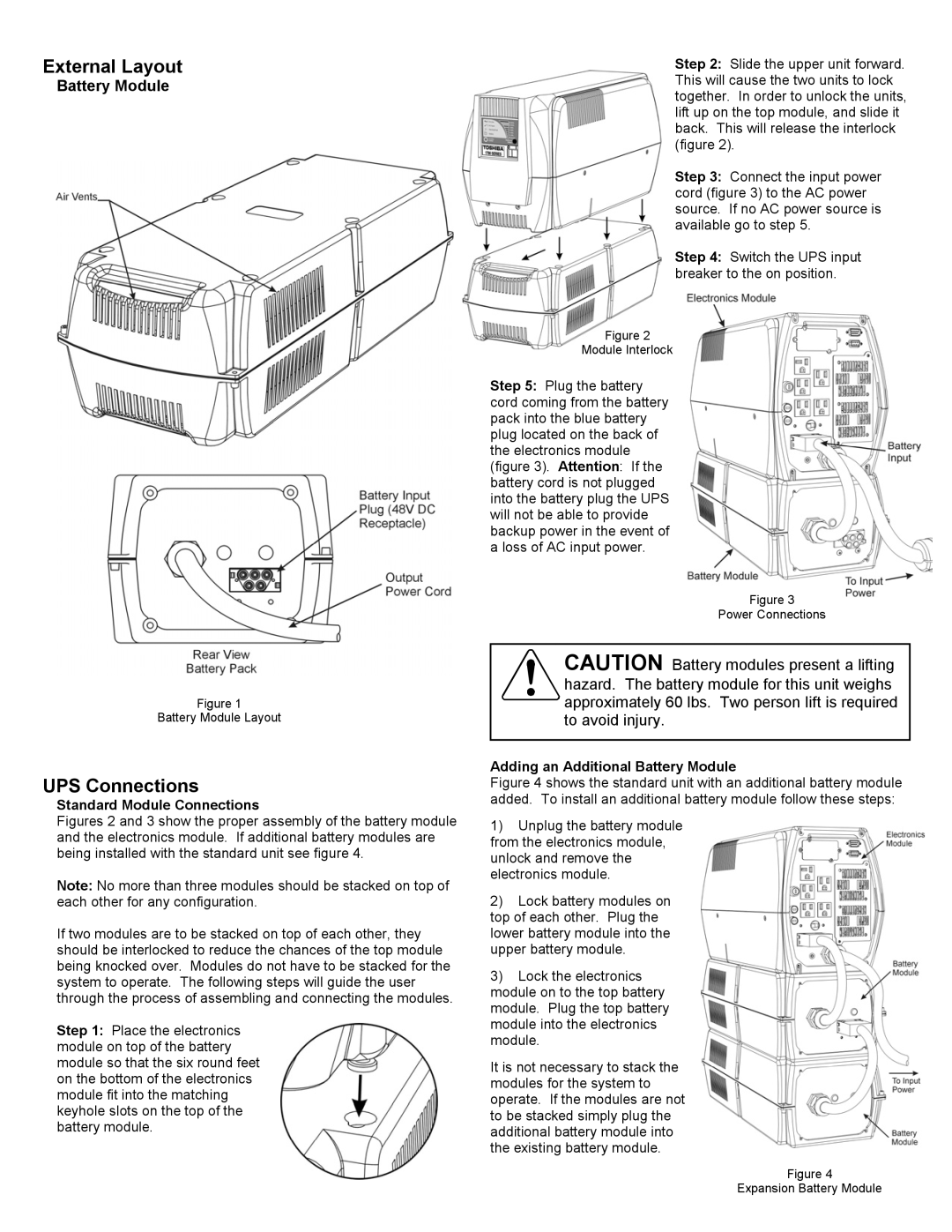
Step 2: Slide the upper unit forward. This will cause the two units to lock together. In order to unlock the units, lift up on the top module, and slide it back. This will release the interlock (figure 2).
Step 3: Connect the input power cord (figure 3) to the AC power source. If no AC power source is available go to step 5.
Step 4: Switch the UPS input breaker to the on position.
Figure 1
Battery Module Layout
UPS Connections
Standard Module Connections
Figures 2 and 3 show the proper assembly of the battery module and the electronics module. If additional battery modules are being installed with the standard unit see figure 4.
Note: No more than three modules should be stacked on top of each other for any configuration.
If two modules are to be stacked on top of each other, they should be interlocked to reduce the chances of the top module being knocked over. Modules do not have to be stacked for the system to operate. The following steps will guide the user through the process of assembling and connecting the modules.
Step 1: Place the electronics module on top of the battery module so that the six round feet on the bottom of the electronics module fit into the matching keyhole slots on the top of the battery module.
Figure 2
Module Interlock
Step 5: Plug the battery cord coming from the battery pack into the blue battery plug located on the back of the electronics module (figure 3). Attention: If the battery cord is not plugged into the battery plug the UPS will not be able to provide backup power in the event of a loss of AC input power.
Figure 3
Power Connections
CAUTION Battery modules present a lifting hazard. The battery module for this unit weighs ![]()
![]() approximately 60 lbs. Two person lift is required
approximately 60 lbs. Two person lift is required
to avoid injury.
Adding an Additional Battery Module
Figure 4 shows the standard unit with an additional battery module added. To install an additional battery module follow these steps:
1)Unplug the battery module from the electronics module, unlock and remove the electronics module.
2)Lock battery modules on top of each other. Plug the lower battery module into the upper battery module.
3)Lock the electronics module on to the top battery module. Plug the top battery module into the electronics module.
It is not necessary to stack the modules for the system to operate. If the modules are not to be stacked simply plug the additional battery module into the existing battery module.
Figure 4
Expansion Battery Module
