Practical operation example
(X1,Y1)
(1)
(2)
(3)
(4)
(5)
(6)
(7)
(X2,Y2)
(X1,Y1) Block A
(1)
(2)
(3)
(4)
(5)
(6)
(7)
(X2,Y2)
(X3,Y3) | Block B |
(8)
(9)
(10)
(11)
(12)
(13)
(14)
(X4,Y4)
(X1,Y1) | Block A |
|
(1) |
|
|
(2) |
|
|
(3) |
|
|
(4) | (X3,Y3) | Block B |
(5) | ||
(6) |
|
|
(7) | (8) |
|
(9) ![]()
![]() (10)
(10)![]()
(11) ![]()
![]() (12)
(12)![]()
(13) ![]()
![]() (14)
(14)![]()
(15) ![]()
![]() (16)
(16)![]()
(17)
(X2,Y2)(18)![]() (19)
(19)![]() (20)
(20)
(X4,Y4)
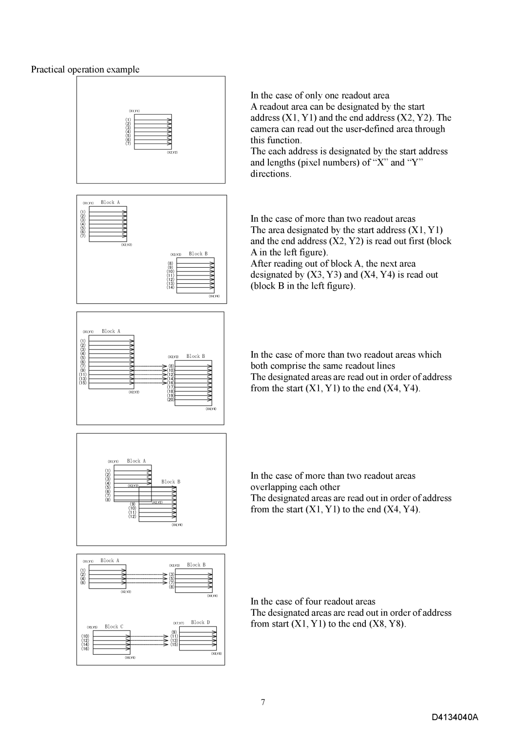
In the case of only one readout area
A readout area can be designated by the start address (X1, Y1) and the end address (X2, Y2). The camera can read out the
The each address is designated by the start address and lengths (pixel numbers) of “X” and “Y” directions.
In the case of more than two readout areas
The area designated by the start address (X1, Y1) and the end address (X2, Y2) is read out first (block A in the left figure).
After reading out of block A, the next area designated by (X3, Y3) and (X4, Y4) is read out (block B in the left figure).
In the case of more than two readout areas which both comprise the same readout lines
The designated areas are read out in order of address from the start (X1, Y1) to the end (X4, Y4).
(X1,Y1) | Block A |
|
(1) |
|
|
(2) |
|
|
(3) |
| Block B |
(4) | (X3,Y3) | |
(5) |
| |
|
| |
(6) |
|
|
(7) |
|
|
(8) | (9) | (X2,Y2) |
| ||
|
| |
| (10) |
|
| (11) |
|
| (12) |
|
|
| (X4,Y4) |
(X1,Y1) | Block A |
| Block B |
|
| (X3,Y3) | |
(1) |
|
|
|
(2) |
| (3) |
|
(4) |
| (5) |
|
(6) |
| (7) |
|
|
| (8) |
|
| (X2,Y2) |
|
|
|
|
| (X4,Y4) |
| Block C | (X7,Y7) | Block D |
(X5,Y5) |
|
| |
|
| (9) |
|
(10) |
| (11) |
|
(12) |
| (13) |
|
(14) |
| (15) |
|
(16) |
|
|
|
|
|
| (X8,Y8) |
| (X6,Y6) |
|
|
In the case of more than two readout areas overlapping each other
The designated areas are read out in order of address from the start (X1, Y1) to the end (X4, Y4).
In the case of four readout areas
The designated areas are read out in order of address from start (X1, Y1) to the end (X8, Y8).
7