Names of each part on the control panel and remote control
Control panel | Remote Control |
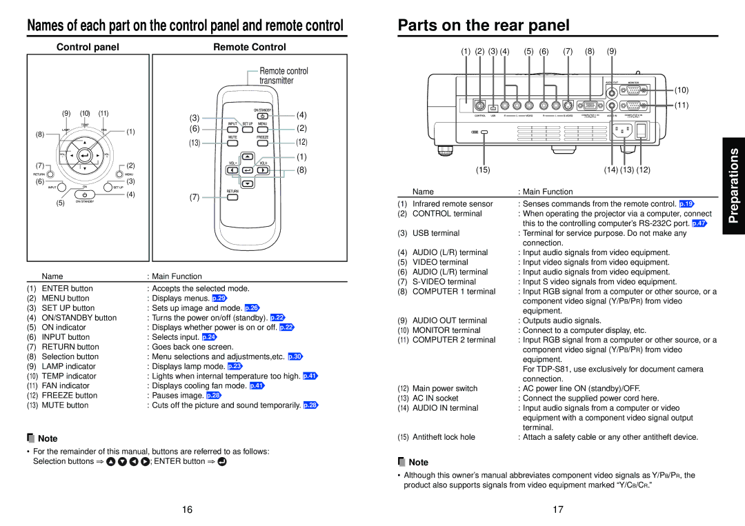
Parts on the rear panel
(1) | (2) | (3) (4) | (5) | (6) | (7) | (8) | (9) |
(9)(10) (11)
(8) | (1) |
| |
(7) | (2) |
(6) | (3) |
| (4) |
| (5) |
| Remote control |
| transmitter |
(3) | (4) |
| |
(6) | (2) |
(13) | (12) |
| (1) |
| (8) |
(7) |
|
(10)
![]()
![]() (11)
(11)
| (15) | (14) (13) (12) |
| Name | : Main Function |
(1) | Infrared remote sensor | : Senses commands from the remote control. p.19 |
(2) | CONTROL terminal | : When operating the projector via a computer, connect |
|
| this to the controlling computer’s |
(3) | USB terminal | : Terminal for service purpose. Do not make any |
|
| connection. |
(4) | AUDIO (L/R) terminal | : Input audio signals from video equipment. |
(5) | VIDEO terminal | : Input video signals from video equipment. |
(6) | AUDIO (L/R) terminal | : Input audio signals from video equipment. |
Preparations
| Name | : Main Function |
(1) | ENTER button | : Accepts the selected mode. |
(2) | MENU button | : Displays menus. p.29 |
(3) | SET UP button | : Sets up image and mode. p.26 |
(4) | ON/STANDBY button | : Turns the power on/off (standby). p.22 |
(5) | ON indicator | : Displays whether power is on or off. p.22 |
(6) | INPUT button | : Selects input. p.24 |
(7) | RETURN button | : Goes back one screen. |
(8) | Selection button | : Menu selections and adjustments,etc. p.30 |
(9) | LAMP indicator | : Displays lamp mode. p.23 |
(10) TEMP indicator | : Lights when internal temperature too high. p.41 | |
(11) FAN indicator | : Displays cooling fan mode. p.41 | |
(12) FREEZE button | : Pauses image. p.28 | |
(13) MUTE button | : Cuts off the picture and sound temporarily. p.28 | |
![]() Note
Note
•For the remainder of this manual, buttons are referred to as follows:
Selection buttons ⇒ ![]()
![]()
![]()
![]() ; ENTER button ⇒
; ENTER button ⇒ ![]()
(7) | : Input S video signals from video equipment. | |
(8) | COMPUTER 1 terminal | : Input RGB signal from a computer or other source, or a |
|
| component video signal (Y/PB/PR) from video |
|
| equipment. |
(9) | AUDIO OUT terminal | : Outputs audio signals. |
(10) | MONITOR terminal | : Connect to a computer display, etc. |
(11) COMPUTER 2 terminal | : Input RGB signal from a computer or other source, or a | |
|
| component video signal (Y/PB/PR) from video |
|
| equipment. |
|
| For |
|
| connection. |
(12) Main power switch | : AC power line ON (standby)/OFF. | |
(13) AC IN socket | : Connect the supplied power cord here. | |
(14) AUDIO IN terminal | : Input audio signals from a computer or video | |
|
| equipment with a component video signal output |
|
| terminal. |
(15) Antitheft lock hole | : Attach a safety cable or any other antitheft device. | |
![]() Note
Note
•Although this owner’s manual abbreviates component video signals as Y/PB/PR, the product also supports signals from video equipment marked “Y/CB/CR.”
16 | 17 |