P0325 specifications
The Toyota P0325 is a diagnostic trouble code (DTC) that pertains to the vehicle's Knock Sensor (KS) circuit malfunction. This particular code is crucial for ensuring that the vehicle's engine operates effectively. The knock sensor is vital in detecting engine knock or pre-ignition, which occurs when fuel combusts prematurely in the engine cylinder. This problem can lead to severe engine damage if not addressed timely.Key features of the P0325 code include its focus on the knock sensor's function, which serves as a critical component in the engine management system. A properly functioning knock sensor allows the engine control unit (ECU) to adjust ignition timing and optimize engine performance. This adjustment helps improve engine efficiency and reduce emissions, making it essential for both performance and environmental considerations.
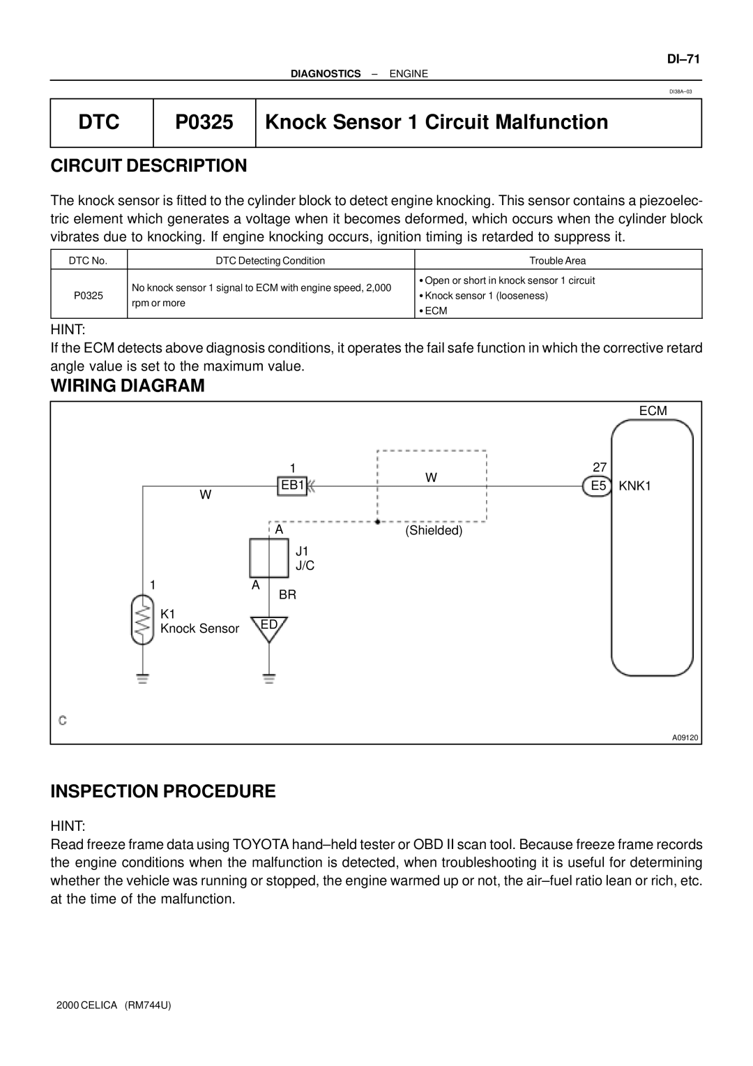
The technologies involved in the knock sensor system include piezoelectric materials that generate a voltage signal when they detect engine vibrations associated with knocking. This signal is sent to the ECU, which interprets it and adjusts the engine's ignition timing as needed. If the ECU receives an abnormal reading or no signal from the knock sensor, it triggers the P0325 code, indicating a malfunction.
Common characteristics of vehicles experiencing a P0325 code include a noticeable decrease in engine performance, reduced fuel economy, and increased emissions. In some cases, the vehicle may exhibit rough idling or knocking noises, particularly under acceleration or high load conditions. Pay attention to these symptoms as they can impact the overall driving experience and long-term engine health.
To resolve a P0325 code, it is essential to conduct a thorough diagnostic evaluation to determine the root cause. Potential fixes may include replacing the knock sensor, checking the wiring and connections for damage, or addressing any underlying engine issues contributing to knocking. Regular maintenance and timely diagnostics can help prevent the occurrence of the P0325 code, ensuring that the vehicle runs smoothly and efficiently.
In conclusion, the Toyota P0325 code relates to the knock sensor circuit malfunction, playing a critical role in engine performance and efficiency. Understanding the features, technologies, and potential issues associated with this DTC is vital for maintaining the health of your vehicle and ensuring a smooth driving experience. Regular attention to the knock sensor and associated components can help keep your Toyota running at its best.