SDHC Card series
4~32GB High Capacity Secure Digital Card
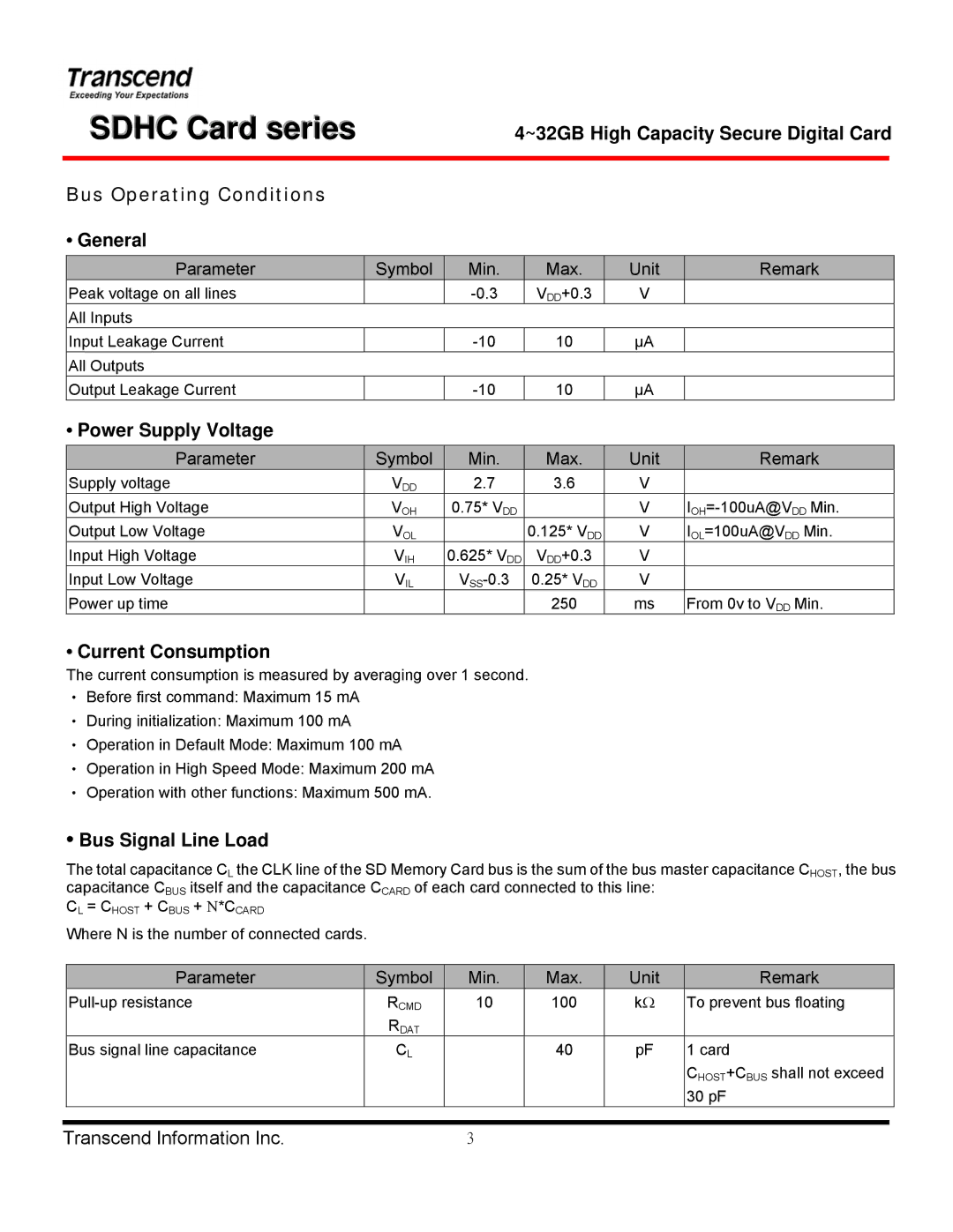
Bus Operating Conditions
• General
Parameter | Symbol |
| Min. | Max. | Unit |
Peak voltage on all lines |
| VDD+0.3 | V | ||
All Inputs |
|
|
|
|
|
Input Leakage Current |
|
| 10 | µA | |
All Outputs |
|
|
|
|
|
Output Leakage Current |
|
| 10 | µA | |
•Power Supply Voltage
Parameter | Symbol | Min. | Max. | Unit |
Supply voltage | VDD | 2.7 | 3.6 | V |
Output High Voltage | VOH | 0.75* VDD |
| V |
Output Low Voltage | VOL |
| 0.125* VDD | V |
Input High Voltage | VIH | 0.625* VDD | VDD+0.3 | V |
Input Low Voltage | VIL | 0.25* VDD | V | |
Power up time |
|
| 250 | ms |
Remark
Remark
From 0v to VDD Min.
•Current Consumption
The current consumption is measured by averaging over 1 second.
‧Before first command: Maximum 15 mA
‧During initialization: Maximum 100 mA
‧Operation in Default Mode: Maximum 100 mA
‧Operation in High Speed Mode: Maximum 200 mA
‧Operation with other functions: Maximum 500 mA.
•Bus Signal Line Load
The total capacitance CL the CLK line of the SD Memory Card bus is the sum of the bus master capacitance CHOST, the bus capacitance CBUS itself and the capacitance CCARD of each card connected to this line:
CL = CHOST + CBUS + Ν*CCARD
Where N is the number of connected cards.
Parameter | Symbol | Min. | Max. | Unit |
RCMD | 10 | 100 | kΩ | |
| RDAT |
|
|
|
Bus signal line capacitance | CL |
| 40 | pF |
|
|
|
|
|
Remark
To prevent bus floating
1 card
CHOST+CBUS shall not exceed 30 pF
Transcend Information Inc. | 3 |