CBFTF10xx-15x
INSTALLATION
CAUTION: Wear a grounding device and observe electrostatic discharge precautions when setting the
INSTALLATION -- Continued
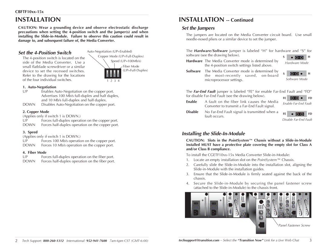
Set the Jumpers
The jumpers are located on the Media Converter circuit board. Use small
Set the 4-Position Switch
The
Copper Mode
Speed (UP=100Mb/s)
Fiber Mode
1 2 3 4
The Hardware/Software jumper is labeled “H” for hardware and “S” for
software (see the drawing below).H
S
Hardware | The Media Converter mode is determined by |
| Hardware Mode | ||||
| the |
| |||||
|
|
|
|
|
|
| |
Software | The Media Converter mode is determined by | S |
|
|
|
| H |
|
|
|
| ||||
|
|
|
| ||||
| the |
|
|
|
| ||
|
| Software Mode | |||||
| microprocessor settings. |
| |||||
1. Auto-Negotiation
UP | Enables |
| Advertises 100 Mb/s |
| and 10 Mb/s |
DOWN | Disables |
2. Copper Mode
(Applies only if switch 1 is DOWN.)
UP | Forces |
DOWN | Forces |
3. Speed
(Applies only if switch 1 is DOWN.)
UP | Forces 100 Mb/s operation on the copper port. |
DOWN | Forces 10 Mb/s operation on the copper port. |
4. Fiber Mode | |
UP | Forces |
DOWN | Forces |
The
for disable
FEFD
Enable | A fault on the fiber link causes the Media | Enable | |
| Converter to transmit a | ||
|
|
| |
Disable | No | FE | FD |
| fault occurs. | ||
|
|
| |
Disable
Installing the Slide-In-Module
CAUTION: Slots in the PointSystem™ Chassis without a
To install the
1.Locate an empty installation slot on the PointSystem™ Chassis.
2.Carefully slide the
3.Ensure that the
4.Secure the
|
| TX PWR |
| PWR |
|
| PWR |
| PWR | PWR |
|
| |
|
|
|
| LA | LKS | PWR | LKS | LA | LKS | SPD | PWR | ||
|
|
|
|
| LNK |
|
|
|
| LNK |
|
|
|
|
|
|
| RXF |
| LKM | FLNK | LKM | RXF |
| LKM | FRX | FLNK |
|
| RX | LNK | RXC | COL |
| CLNK |
| RXC | COL | TX | CRX | CLNK |
|
| R |
|
| Link Alert | TX |
| TX |
| Link Alert |
|
| |
|
| E |
|
|
|
|
| E |
|
|
| ||
|
| S |
| E | D | RXSinglemode |
| RXSinglemode | D | RXSinglemode | TX |
| |
|
| E |
|
|
|
|
|
|
| ||||
I 0 | I 0 | T |
|
|
|
|
|
| |||||
INIT |
| 10/100SX | 10BASE- |
|
| ||||||||
TERM |
|
|
| ||||||||||
|
|
|
| ||||||||||
|
|
|
|
|
| TX |
| TX | FL |
| TX | RX |
|
|
|
|
|
|
|
|
|
|
|
| |||
|
| SERIAL |
| 0 | 50½ | Multimode |
| Multimode | 0 | 50½ | Multimode |
| |
|
|
|
|
| 10BASE- |
|
| ||||||
|
|
|
| RX |
| RX |
| RX |
| ||||
|
|
|
|
|
|
|
|
| 2 |
|
|
|
|
|
| CPSMM120 | CECF100 |
| CFETF110 | CFMFF100 | CETCF100 | CFMFF100 | CFETF100 | ||||
Panel Fastener Screw
2 Tech Support: | techsupport@transition.com | 3 |