SAPTF33xx-1xx

Installation -- Continued

Grounding the Media Converter

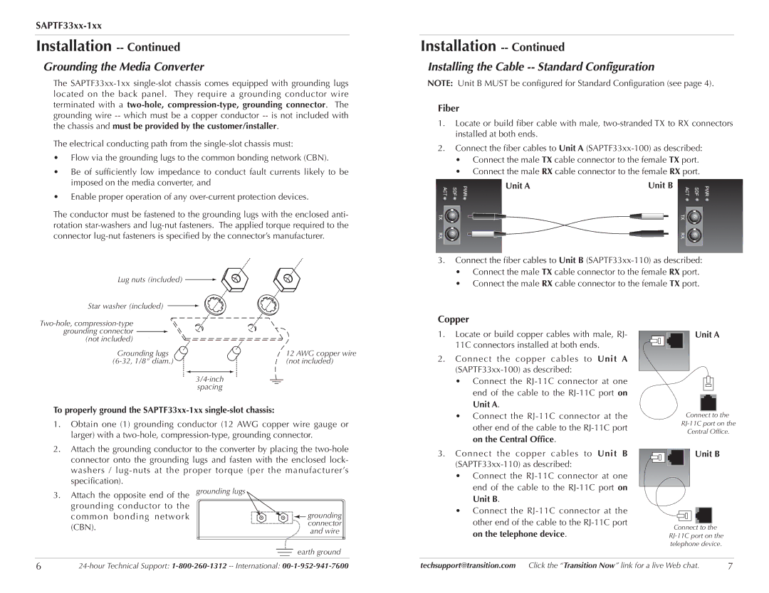
The SAPTF33xx-1xx single-slot chassis comes equipped with grounding lugs located on the back panel. They require a grounding conductor wire terminated with a two-hole,compression-type, grounding connector. The grounding wire -- which must be a copper conductor -- is not included with the chassis and must be provided by the customer/installer.

The electrical conducting path from the single-slot chassis must:

Flow via the grounding lugs to the common bonding network (CBN).

Be of sufficiently low impedance to conduct fault currents likely to be imposed on the media converter, and

Enable proper operation of any over-current protection devices.

The conductor must be fastened to the grounding lugs with the enclosed anti- rotation star-washers and lug-nut fasteners. The applied torque required to the connector lug-nut fasteners is specified by the connector’s manufacturer.

Lug nuts (included)

Star washer (included)

Two-hole, compression-type grounding connector

(not included)

Grounding lugs

12 AWG copper wire

(6-32, 1/8" diam.)

(not included)

3/4-inch

spacing

To properly ground the SAPTF33xx-1xx single-slot chassis:

1.Obtain one (1) grounding conductor (12 AWG copper wire gauge or larger) with a two-hole, compression-type, grounding connector.

2.Attach the grounding conductor to the converter by placing the two-hole connector onto the grounding lugs and fasten with the enclosed lock- washers / lug-nuts at the proper torque (per the manufacturer’s specification).

3.Attach the opposite end of the grounding lugs grounding conductor to the

common bonding network

grounding

(CBN).

connector

and wire


earth ground

Installation -- Continued

Installing the Cable -- Standard Configuration

NOTE: Unit B MUST be configured for Standard Configuration (see page 4).

Fiber

1.Locate or build fiber cable with male, two-stranded TX to RX connectors installed at both ends.

2.Connect the fiber cables to Unit A (SAPTF33xx-100) as described:

Connect the male TX cable connector to the female TX port.

Connect the male RX cable connector to the female RX port.

ACT

SDF

PWR

Unit A

Unit B

ACT

SDF

PWR


TX


TX


RX


RX


3.Connect the fiber cables to Unit B (SAPTF33xx-110) as described:

Connect the male TX cable connector to the female RX port.

Connect the male RX cable connector to the female TX port.

Copper


1. Locate or build copper cables with male, RJ-


Unit A

11C connectors installed at both ends.


2. Connect the copper cables to Unit A


(SAPTF33xx-100) as described:


• Connect the RJ-11C connector at one


end of the cable to the RJ-11C port on


Unit A.


• Connect the RJ-11C connector at the


Connect to

the

other end of the cable to the RJ-11C port


RJ-11C port on the


Central Office.

on the Central Office.


3. Connect the copper cables to Unit B


Unit B


(SAPTF33xx-110) as described:


• Connect the RJ-11C connector at one


end of the cable to the RJ-11C port on


Unit B.


• Connect the RJ-11C connector at the


other end of the cable to the RJ-11C port


Connect to the

on the telephone device.


RJ-11C port on the

telephone device.

6

24-hour Technical Support: 1-800-260-1312-- International: 00-1-952-941-7600

techsupport@transition.com Click the “Transition Now” link for a live Web chat.

7

Page 2
Image 2
Transition Networks SAPTF33xx-100 Grounding the Media Converter, Installing the Cable -- Standard Configuration, Fiber

SAPTF33xx-110, SAPTF33xx-100 specifications

Transition Networks has made significant strides in the field of network communications with their SAPTF33xx-100 and SAPTF33xx-110 series of media converters. These devices are designed to facilitate a seamless transition between different types of network connections, specifically converting between twisted pair Ethernet and fiber optic cabling. This capability is crucial for organizations seeking to extend the reach of their networks while maintaining high-speed communication.

One of the standout features of the SAPTF33xx series is its support for both 10/100/1000 Mbps speeds, making it highly versatile for various networking needs. The devices can operate in both half-duplex and full-duplex modes, providing flexibility in how networks are managed. This adaptability allows users to choose the configuration best suited to their specific operational environment.

The SAPTF33xx-100 model is tailored for applications that require fast and reliable data transfer over shorter distances, utilizing twisted pair cabling. In contrast, the SAPTF33xx-110 extends this capability by integrating fiber optic connections, which are essential for long-distance data transmission. This feature is particularly beneficial in environments where electromagnetic interference (EMI) is a concern, as fiber optic cables are impervious to such disturbances.

Another impressive characteristic of these media converters is their plug-and-play functionality. This feature simplifies setup and operation, requiring minimal configuration, which is appealing for organizations without extensive IT support. Additionally, both devices are equipped with LED indicators that provide real-time diagnostics, enabling users to monitor network status and troubleshoot issues effectively.

The SAPTF33xx series also boasts robust build quality, with various mounting options to fit different rack sizes and environments. They are designed for long-term durability and can withstand the rigors of different operational settings, whether in data centers or remote installations.

Moreover, these devices come with enhanced features such as auto-negotiation, which simplifies network configuration by automatically selecting the optimal transmission speed and duplex mode. This automaticity ensures that the devices maintain optimal performance without requiring manual intervention from network administrators.

In summary, Transition Networks’ SAPTF33xx-100 and SAPTF33xx-110 media converters represent a reliable solution for organizations looking to enhance their network infrastructure. With their high-speed capabilities, seamless integration of copper and fiber connections, ease of use, and robust design, these devices stand out as impactful tools for improving network efficiency and reliability.