
TEG-448WS specifications
The TRENDnet TEG-448WS is a robust and efficient 48-port Gigabit switch designed to meet the demands of enterprise-class networking. Ideal for businesses seeking reliable, high-speed connectivity, the TEG-448WS streamlines network management while enhancing performance and versatility in data handling.One of the standout features of the TEG-448WS is its Layer 2 switching capabilities. With support for various Layer 2 protocols, including VLANs (Virtual Local Area Networks), the switch allows for segmentation of networks, improving both security and performance. Administrators can easily create VLANs to group devices logically, thus optimizing bandwidth usage while reducing congestion.
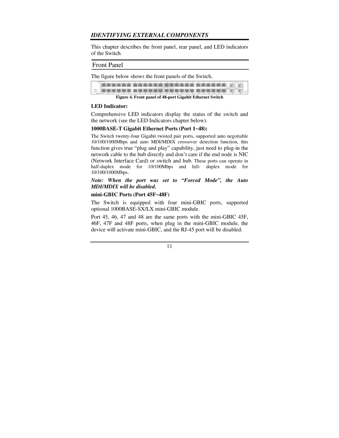
The switch supports a high-density design, featuring 48 Gigabit Ethernet ports, which helps businesses expand their local area network without compromising on speed. Additionally, the compact 1U rack-mountable design makes it a perfect fit for data centers and server rooms, maximizing space efficiency while maintaining easy accessibility.
Power over Ethernet (PoE) capability further enhances the TEG-448WS, allowing it to deliver power and data through the same Ethernet cable to PoE-enabled devices like IP cameras, VoIP phones, and wireless access points. This feature can significantly reduce installation costs and simplify the deployment of network devices.
The device also includes advanced management features such as Quality of Service (QoS) for traffic prioritization, enabling smoother performance for latency-sensitive applications like video conferencing and VoIP. The switch supports advanced security features like Access Control Lists (ACLs) and port security, providing businesses with the necessary tools to protect their network from unauthorized access.
Another key characteristic of the TRENDnet TEG-448WS is its fanless design, which ensures that the switch operates quietly, making it an excellent choice for office environments. This design also contributes to energy efficiency, helping to reduce operational costs and overall environmental impact.
With its combination of high performance, advanced features, and ease of management, the TRENDnet TEG-448WS stands out as a compelling choice for businesses looking to upgrade their networking infrastructure. Its ability to cater to various network settings while providing reliable performance makes it a valuable asset in any organizational context.