SET-UP
This unit is shipped WITHOUT GASOLINE or OIL. After assembly, service engine with gasoline and oil as instructed in the separate engine manual packed with your unit.
NOTE: Reference to right or left hand side of the mower is observed from the operating position.
This owner’s manual covers various models of lawnmowers. The units illustrated may vary slightly from your unit. Follow only those instructions which pertain to your model lawnmower.
• Disconnect the spark plug wire and ground it as in- |
structed in the separate engine manual packed with |
your unit. |
Remove the carton inserts (if any). Remove the loose |
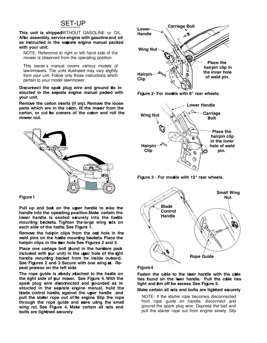
Carriage Bolt
Lower ![]()
Handle
Wing Nut ![]()
Place the
hairpin clip in
![]()
![]()
![]()
![]()
![]()
![]()
![]()
![]()
![]()
![]() the inner hole Hairpin
the inner hole Hairpin ![]()
![]()
![]()
![]()
![]()
![]()
of weld pin.
Clip
Figure 2- For models with 8" rear wheels.
• |
parts which are in the carton, lift the mower from the |
carton, or cut the corners of the carton and roll the |
mower out. |
Wing Nut
Hairpin 
 Clip
Clip
 Lower Handle


 Carriage
Bolt


 Place the
hairpin clip
in the inner


 hole of weld


 pin.
pin.
Figure 1
•Pull up and back on the upper handle to raise the handle into the operating position. Make certain the lower handle is seated securely into the handle mounting brackets. Tighten the large wing nuts on each side of the handle. See Figure 1.
•Remove the hairpin clips from the outer hole in the weld pins on the handle mounting brackets. Place the hairpin clips in the inner hole. See Figures 2 and 3.
•Place one carriage bolt (found in the hardware pack included with your unit) in the upper hole of the right handle mounting bracket from the inside outward. See Figures 2 and 3. Secure with one wing nut. Re- peat process on the left side.
•The rope guide is already attached to the handle on the right side of your mower. See Figure 4. With the spark plug wire disconnected and grounded as in- structed in the separate engine manual, hold the blade control handle, against the upper handle and pull the starter rope out of the engine. Slip the rope through the rope guide and secure using the small wing nut. See Figure 4. Make certain all nuts and bolts are tightened securely.
Figure 3 - For models with 12" rear wheels.
Small Wing
Nut
Blade
Control
Handle
Rope Guide
Figure 4
•Fasten the cable to the lower handle with the cable ties found on the lower handle. Pull the cable ties tight and trim off the excess. See Figure 5.
•Make certain all nuts and bolts are tightened securely.
NOTE: If the starter rope becomes disconnected from rope guide on handle, disconnect and ground the spark plug wire. Depress the bail and pull the starter rope out from engine slowly. Slip
6