6
Section
3
Features and Controls
OPERATING SYMBOLS
Various symbols (shown here, with word descriptions) are used on the unit.
STOP
ENGINE | FAST | SLOW | STOP | TRIMMER |
STOP |
|
|
| HEAD |
ENGAGE DISENGAGE
BAILBAIL
WARNING
Before operating your machine, care- fully read and understand all safety, controls and operating instructions in this Manual, the separate Engine Owner’s Manual, and on the decals on the machine.
Failure to follow these instructions can result in serious personal injury.
Handlebar Height Adjustment
The handlebar (D, Figure
Plastic Debris Shield
A
Fuel Primer Button
The fuel primer button (H, Figure
E
FEATURES AND CONTROLS
This Section describes the location and function of the features and controls on your machine. Refer to the “Operation” Section for detailed operating instructions.
IMPORTANT: Refer to the separate en- gine manual for detailed information about the controls on the engine.
Engine Throttle Control Lever
Use this lever (F, Figure
Engine Recoil Starter
The recoil starter is located at the rear of the engine (G, Figure
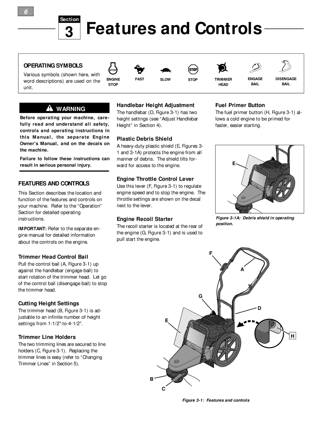
Figure 3-1A: Debris shield in operating position.
Trimmer Head Control Bail
Pull the control bail (A, Figure
Cutting Height Settings
The trimmer head (B, Figure
Trimmer Line Holders
The two trimming lines are secured to line holders (C, Figure
F
A
G
![]() D
D
E
H
B![]()
![]()
C