Section 3: Features and Controls
Depth Regulator Lever
This lever (G, Figure
The highest notch (lever all the way down) raises the tines approximately 1- 1/2" off the ground. This “travel” setting allows the tiller to be moved without the tines digging into the ground. Also use this setting when starting the engine.
Move the lever upward to increase the tilling depth. The lowest notch allows a tilling depth of approximately
For best results, begin tilling at the deepest depth possible without causing the tiller to bog down. Increase the tilling depth from one pass over the soil to the next.
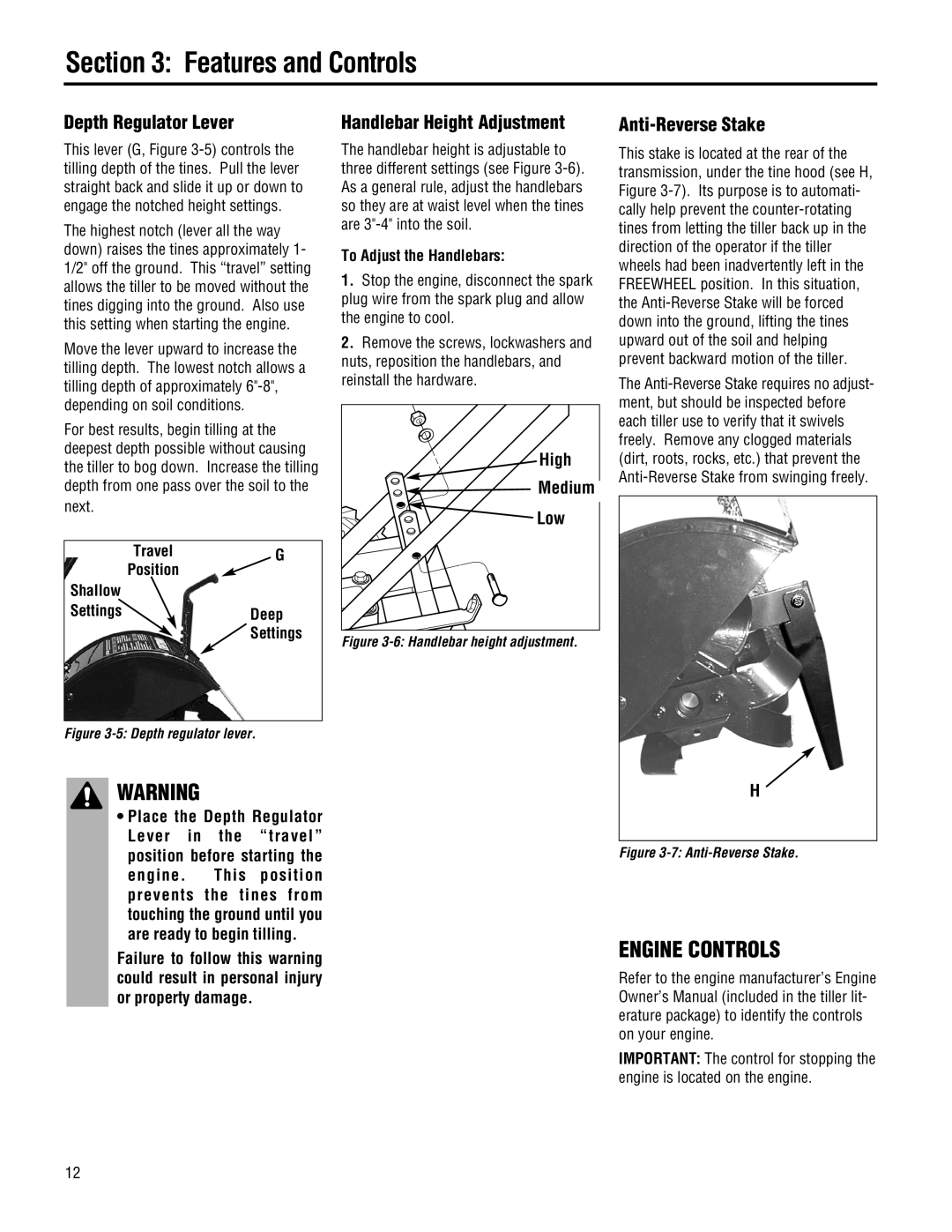
Travel | G |
Position |
|
Shallow |
|
Settings | Deep |
| Settings |
Figure 3-5: Depth regulator lever.
WARNING
•Place the Depth Regulator Lever in the “travel” position before starting the
engine. This position prevents the tines from touching the ground until you are ready to begin tilling.
Failure to follow this warning could result in personal injury or property damage.
Handlebar Height Adjustment
The handlebar height is adjustable to three different settings (see Figure
To Adjust the Handlebars:
1.Stop the engine, disconnect the spark plug wire from the spark plug and allow the engine to cool.
2.Remove the screws, lockwashers and nuts, reposition the handlebars, and reinstall the hardware.
High |
Medium |
Low |
Figure 3-6: Handlebar height adjustment.
Anti-Reverse Stake
This stake is located at the rear of the transmission, under the tine hood (see H, Figure
The
H
Figure 3-7: Anti-Reverse Stake.
ENGINE CONTROLS
Refer to the engine manufacturer’s Engine Owner’s Manual (included in the tiller lit- erature package) to identify the controls on your engine.
IMPORTANT: The control for stopping the engine is located on the engine.
12