8Section 2: Assembly

CAUTION

Incorrect cable adjustment could cause the wheels and tines to rotate unexpect- edly. Follow adjustment procedures carefully. Failure to do so could result in personal injury or property damage.

4.Check for correct spring/cable tension as instructed in Section 5, Checking and Adjusting Forward Clutch Belt Tension.

5.When tension is correct, tighten the two jam nuts (B) securely.

STEP 5: CHECK TRANSMISSION GEAR OIL LEVEL

The transmission was filled with gear oil at the factory. However, be sure to check the oil level at this time to make certain it is correct.

IMPORTANT: Do not operate the tiller if the gear oil level is low. Doing so will result in severe damage to the transmis- sion components.

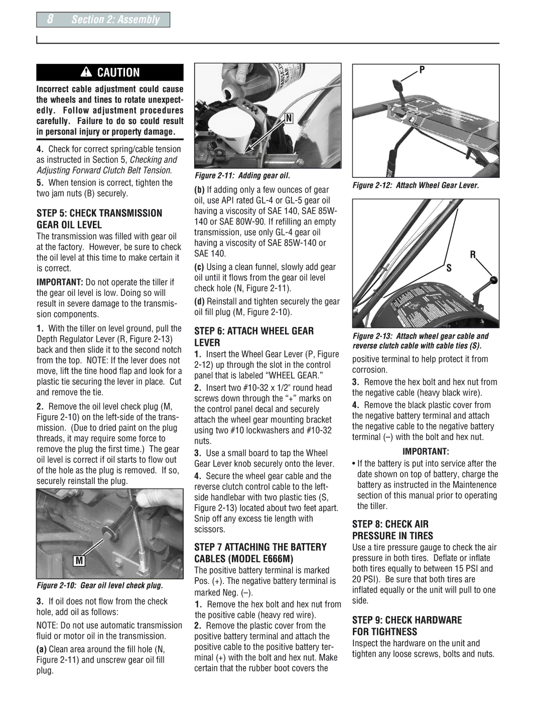
1.With the tiller on level ground, pull the Depth Regulator Lever (R, Figure 2-13) back and then slide it to the second notch from the top. NOTE: If the lever does not move, lift the tine hood flap and look for a plastic tie securing the lever in place. Cut and remove the tie.

2.Remove the oil level check plug (M, Figure 2-10) on the left-side of the trans- mission. (Due to dried paint on the plug threads, it may require some force to remove the plug the first time.) The gear oil level is correct if oil starts to flow out of the hole as the plug is removed. If so, securely reinstall the plug.

M

Figure 2-10: Gear oil level check plug.

3.If oil does not flow from the check hole, add oil as follows:

NOTE: Do not use automatic transmission fluid or motor oil in the transmission.

(a)Clean area around the fill hole (N, Figure 2-11) and unscrew gear oil fill plug.

N

Figure 2-11: Adding gear oil.

(b)If adding only a few ounces of gear oil, use API rated GL-4 or GL-5 gear oil having a viscosity of SAE 140, SAE 85W- 140 or SAE 80W-90. If refilling an empty transmission, use only GL-4 gear oil having a viscosity of SAE 85W-140 or SAE 140.

(c)Using a clean funnel, slowly add gear oil until it flows from the gear oil level check hole (N, Figure 2-11).

(d)Reinstall and tighten securely the gear oil fill plug (M, Figure 2-10).

STEP 6: ATTACH WHEEL GEAR LEVER

1.Insert the Wheel Gear Lever (P, Figure 2-12) up through the slot in the control panel that is labeled “WHEEL GEAR.”

2.Insert two #10-32 x 1/2" round head screws down through the “+” marks on the control panel decal and securely attach the wheel gear mounting bracket using two #10 lockwashers and #10-32 nuts.

3.Use a small board to tap the Wheel Gear Lever knob securely onto the lever.

4.Secure the wheel gear cable and the reverse clutch control cable to the left- side handlebar with two plastic ties (S, Figure 2-13) located about two feet apart. Snip off any excess tie length with scissors.

STEP 7 ATTACHING THE BATTERY CABLES (MODEL E666M)

The positive battery terminal is marked Pos. (+). The negative battery terminal is

marked Neg. (–).

1.Remove the hex bolt and hex nut from the positive cable (heavy red wire).

2.Remove the plastic cover from the positive battery terminal and attach the positive cable to the positive battery ter- minal (+) with the bolt and hex nut. Make certain that the rubber boot covers the

P

Figure 2-12: Attach Wheel Gear Lever.

R

S

Figure 2-13: Attach wheel gear cable and reverse clutch cable with cable ties (S).

positive terminal to help protect it from corrosion.

3.Remove the hex bolt and hex nut from the negative cable (heavy black wire).

4.Remove the black plastic cover from the negative battery terminal and attach the negative cable to the negative battery terminal (–) with the bolt and hex nut.

IMPORTANT:

If the battery is put into service after the date shown on top of battery, charge the battery as instructed in the Maintenence section of this manual prior to operating the tiller.

STEP 8: CHECK AIR

PRESSURE IN TIRES

Use a tire pressure gauge to check the air pressure in both tires. Deflate or inflate both tires equally to between 15 PSI and 20 PSI). Be sure that both tires are inflated equally or the unit will pull to one side.

STEP 9: CHECK HARDWARE FOR TIGHTNESS

Inspect the hardware on the unit and tighten any loose screws, bolts and nuts.

Page 8
Image 8
Troy-Bilt E666M, 664D, 665B manual Assembly, Attach Wheel Gear Lever, Check AIR Pressure in Tires, Marked Neg

E666M, 665B, 664D specifications

Troy-Bilt is a trusted name in outdoor power equipment, and their line of tillers, including the E666M, 664D, and 665B models, exemplifies their commitment to quality and practicality. These tillers are designed to make soil preparation easier and more efficient, catering to both amateur gardeners and seasoned landscapers alike.

The Troy-Bilt E666M is a robust machine tailored for ease of use and reliability. With a powerful engine, it delivers consistent performance, ensuring that users can tackle even the toughest soils. One of its standout features is the adjustable tilling width, which provides flexibility for various gardening needs. This tiller also boasts a Reverse Tillage feature, allowing the operator to break up stubborn soil with ease while enhancing control during operation.

The 664D model takes efficiency a step further with its durable construction and user-friendly design. This tiller is equipped with a dependable engine that provides ample power for deep soil cultivation. The 664D features self-propulsion technology, allowing users to maintain steady speed without exerting excessive effort. The adjustable depth settings further enhance soil penetration, making it possible to cultivate deep for extensive planting or surface till for lighter gardening tasks.

With the 665B, Troy-Bilt introduces advanced engineering for increased maneuverability and performance. This tiller features a patented belt-drive system that improves torque and ensures optimal power transfer to the tines. The 665B is also designed with comfort in mind, featuring ergonomic handles that reduce strain on the operator, making it ideal for longer gardening sessions. Its heavy-duty tines ensure exceptional soil mixing, while the adjustable tilling width and depth allow for customization according to specific gardening requirements.

All three tillers come equipped with Troy-Bilt's signature red oversized drag stake, enabling users to control tilling depth and improve stability during operation. They are designed with durable components that promise longevity and reliability, ensuring that they can withstand rigorous use season after season.

In summary, the Troy-Bilt E666M, 664D, and 665B tillers offer a variety of features and technologies that cater to every gardening need. With their reliable engines, user-friendly designs, and advanced tilling capabilities, these models embody the innovation and durability that Troy-Bilt is known for, making them excellent choices for anyone looking to elevate their gardening experience.