user manual
QLight series
the loudspeaker. The point at which the scaffold clamp is attached to the flybar determines the vertical angle of the loudspeaker as shown in the table following.
The following table gives the predicted downward angle of the enclosure using the various attachment points on the
Attachment position | Vertical angle (negative angle denotes upwards) |
|
|
Hole number 1 (front of cabinet) | |
|
|
Hole number 2 | |
|
|
Hole number 3 | |
|
|
Hole number 4 | |
|
|
Hole number 5 | |
|
|
Hole number 6 | 4° |
|
|
Hole number 7 | 11° |
|
|
Hole number 8 | 18° |
|
|
Hole number 9 | 24° |
|
|
Hole number 10 | 30° |
|
|
Hole number 11 | 35° |
|
|
Hole number 12 (rear of cabinet) | 40° |
|
|
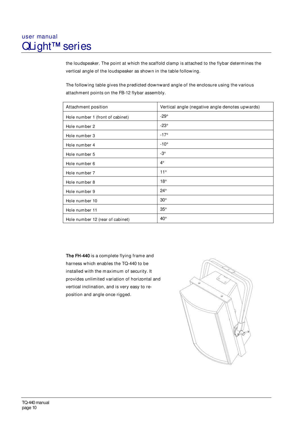
The