Assembly and Installation
1.Uncrate and/or unpack the heater, removing all packing material, being careful not to dispose of the Parts Bag.
2.Remove the following contents:
A.(4) Legs with nut and bolt package
B.(1) Lid with (1) Lid Lifter
C.(1) Shaker Grate
D.(1) Ash Door with (1) Slide Draft
E.(1) Feed Door
3.Carefully lay the stove on its side, preferably on a soft surface. Note: Cardboard shipping carton placed flat works well for this application.
4.Securely attach all four (4) legs to lower chamber using nut and bolt package.
5.Carefully return stove to upright position and place it in desired location.
6.Place lid in position on top plate.
7.Position ash door with slide draft on front of lower chamber.
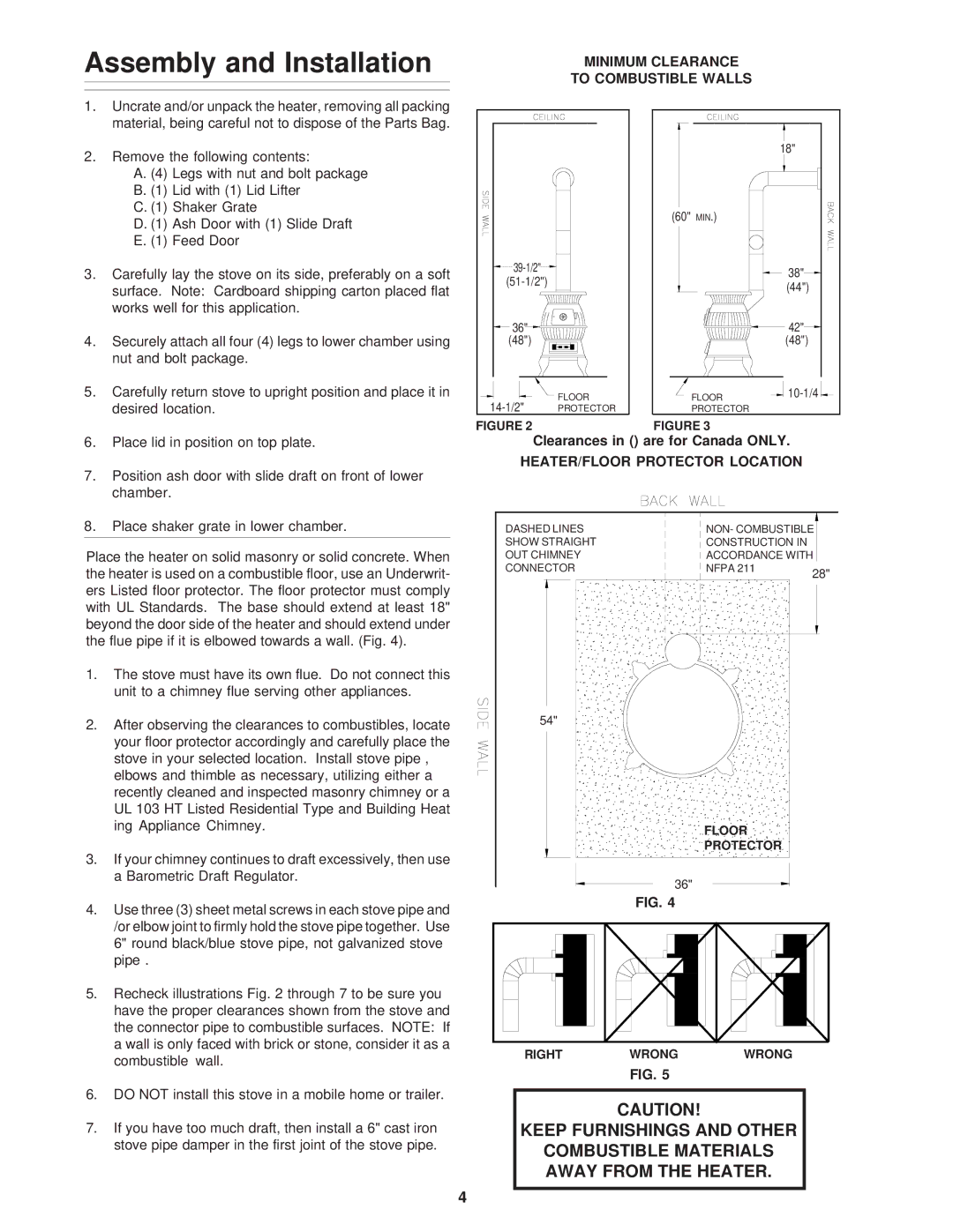
| MINIMUM CLEARANCE |
| |
| TO COMBUSTIBLE WALLS |
| |
|
|
| 18" |
| (60" | MIN.) |
|
|
| 38" | |
|
| ||
|
| (44") | |
|
|
| |
36" |
|
| 42" |
(48") |
|
| (48") |
FLOOR | FLOOR | ||
PROTECTOR | PROTECTOR |
| |
FIGURE 2 | FIGURE 3 |
Clearances in () are for Canada ONLY.
HEATER/FLOOR PROTECTOR LOCATION
8.Place shaker grate in lower chamber.
Place the heater on solid masonry or solid concrete. When the heater is used on a combustible floor, use an Underwrit- ers Listed floor protector. The floor protector must comply with UL Standards. The base should extend at least 18" beyond the door side of the heater and should extend under the flue pipe if it is elbowed towards a wall. (Fig. 4).
1. | The stove must have its own flue. Do not connect this |
| unit to a chimney flue serving other appliances. |
2. | After observing the clearances to combustibles, locate |
| your floor protector accordingly and carefully place the |
| stove in your selected location. Install stove pipe , |
| elbows and thimble as necessary, utilizing either a |
| recently cleaned and inspected masonry chimney or a |
| UL 103 HT Listed Residential Type and Building Heat |
DASHED LINES SHOW STRAIGHT OUT CHIMNEY CONNECTOR
54"
NON- COMBUSTIBLE CONSTRUCTION IN ACCORDANCE WITH
NFPA 211 | 28" |
|
| ing Appliance Chimney. |
3. | If your chimney continues to draft excessively, then use |
| a Barometric Draft Regulator. |
4. | Use three (3) sheet metal screws in each stove pipe and |
| /or elbow joint to firmly hold the stove pipe together. Use |
| 6" round black/blue stove pipe, not galvanized stove |
| pipe . |
5. | Recheck illustrations Fig. 2 through 7 to be sure you |
| have the proper clearances shown from the stove and |
| the connector pipe to combustible surfaces. NOTE: If |
| a wall is only faced with brick or stone, consider it as a |
| combustible wall. |
6. | DO NOT install this stove in a mobile home or trailer. |
7. | If you have too much draft, then install a 6" cast iron |
| stove pipe damper in the first joint of the stove pipe. |
4
FLOOR
PROTECTOR
36"
FIG. 4
RIGHT WRONG WRONG
FIG. 5
CAUTION!
KEEP FURNISHINGS AND OTHER
COMBUSTIBLE MATERIALS AWAY FROM THE HEATER.