ADJUSTMENT OF BOWL HEIGHT:
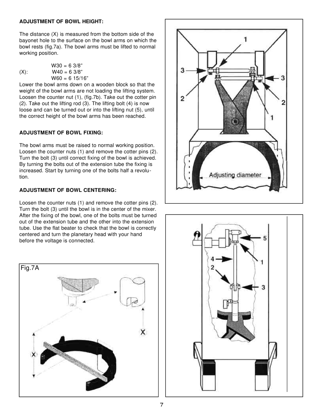
The distance (X) is measured from the bottom side of the bayonet hole to the surface on the bowl arms on which the bowl rests (fig.7a). The bowl arms must be lifted to normal working position.
| W30 = 6 | 3/8” |
(X): | W40 = 6 3/8” | |
| W60 = 6 | 15/16” |
Lower the bowl arms down on a wooden block so that the weight of the bowl arms are not loading the lifting system. Loosen the counter nut (1), (fig.7b). Take out the cotter pin
(2). Take out the lifting rod (3). The lifting bolt (4) is now loose and can be turned out or into the lifting nut (5), until the correct height of the bowl arms has been reached.
ADJUSTMENT OF BOWL FIXING:
The bowl arms must be raised to normal working position. Loosen the counter nuts (1) and remove the cotter pins (2). Turn the bolt (3) until correct fixing of the bowl is achieved. By turning the bolts out of the extension tube the fixing is increased. Start by turning one of the bolts half a revolu- tion.
ADJUSTMENT OF BOWL CENTERING:
Loosen the counter nuts (1) and remove the cotter pins (2). Turn the bolt (3) until the bowl is in the center of the mixer. After the fixing of the bowl, one of the bolts must be turned out of the extension tube and the other into the extension tube. Use the flat beater to check that the bowl is correctly centered and turn the planetary head with your hand before the voltage is connected.
Fig.7A
7
