CONTROLS & CONNECTORS
gChannel Number Indicator
Indicates the operating channel.
Blinks the squelch setting level
hTransceiver Status Indicator
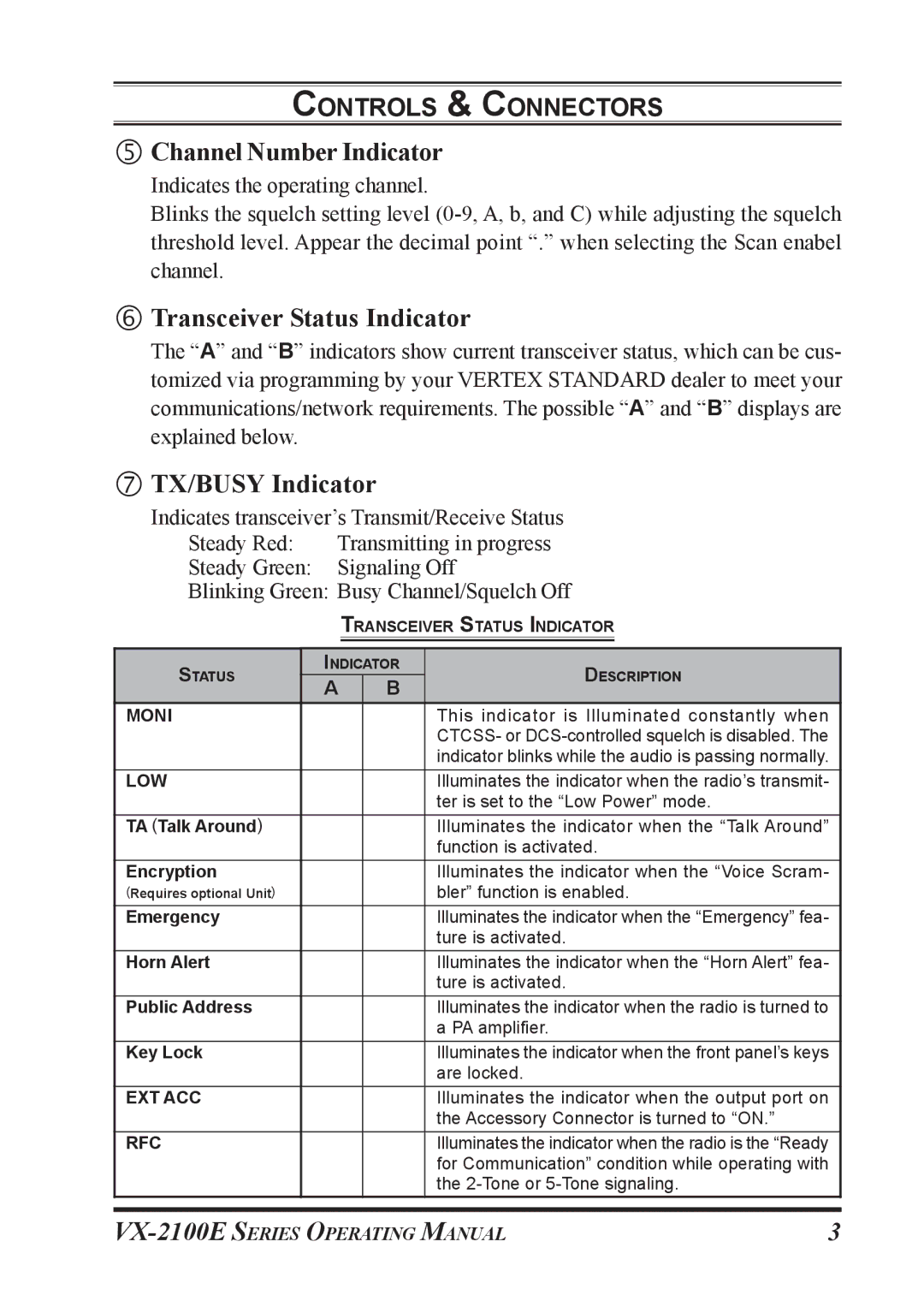
The “A” and “B” indicators show current transceiver status, which can be cus- tomized via programming by your VERTEX STANDARD dealer to meet your communications/network requirements. The possible “A” and “B” displays are explained below.
iTX/BUSY Indicator
Indicates transceiver’s Transmit/Receive Status
Steady Red: | Transmitting in progress | ||||
Steady Green: | Signaling Off | ||||
Blinking Green: Busy Channel/Squelch Off | |||||
|
|
| TRANSCEIVER STATUS INDICATOR | ||
|
|
|
|
| |
STATUS |
| INDICATOR | DESCRIPTION | ||
| A |
| B | ||
|
|
|
| ||
MONI |
|
|
|
| This indicator is Illuminated constantly when |
|
|
|
|
| CTCSS- or |
|
|
|
|
| indicator blinks while the audio is passing normally. |
LOW |
|
|
|
| Illuminates the indicator when the radio’s transmit- |
|
|
|
|
| ter is set to the “Low Power” mode. |
TA (Talk Around) |
|
|
|
| Illuminates the indicator when the “Talk Around” |
|
|
|
|
| function is activated. |
Encryption |
|
|
|
| Illuminates the indicator when the “Voice Scram- |
(Requires optional Unit) |
|
|
|
| bler” function is enabled. |
Emergency |
|
|
|
| Illuminates the indicator when the “Emergency” fea- |
|
|
|
|
| ture is activated. |
Horn Alert |
|
|
|
| Illuminates the indicator when the “Horn Alert” fea- |
|
|
|
|
| ture is activated. |
Public Address |
|
|
|
| Illuminates the indicator when the radio is turned to |
|
|
|
|
| a PA amplifier. |
Key Lock |
|
|
|
| Illuminates the indicator when the front panel’s keys |
|
|
|
|
| are locked. |
EXT ACC |
|
|
|
| Illuminates the indicator when the output port on |
|
|
|
|
| the Accessory Connector is turned to “ON.” |
RFC |
|
|
|
| Illuminates the indicator when the radio is the “Ready |
|
|
|
|
| for Communication” condition while operating with |
|
|
|
|
| the |
|
|
|
|
|
|
3 |