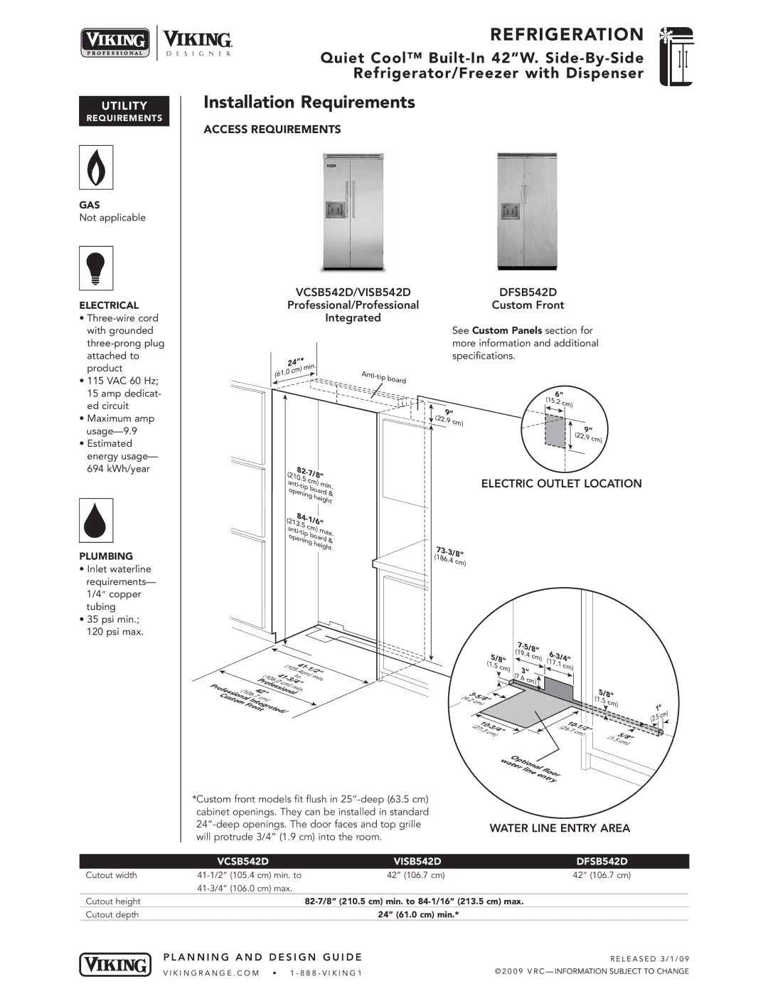
Viking VISB542D, DFSB542D Installation Requirements, Water Line Entry Area, VCSB542D, 73-3, 186

Models: VISB542D DFSB542D VCSB542D

1 8
Download 8 pages 26.88 Kb
Page 7
Image 7

UTILIT Y

REQ UIREME NTS

GAS

Not applicable

ELECTRICAL

Three-wire cord

REFRIG ERATION

Quiet Cool™ Built-In 42”W. Side -By- Side

Refrigerator/Free zer with Dispen ser

Installation Requirements

ACCESS REQUIREMENTS

VCSB542D/VISB542DDFSB542D

Professional/ProfessionalCustom Front

Integrated

with grounded

three-prong plug

attached to

product

• 115 VAC 60 Hz;

15 amp dedicat-

ed circuit

• Maximum amp

usage—9.9

• Estimated

energy usage—

694 kWh/year

PLUMBING

Inlet waterline requirements— 1/4copper tubing

35 psi min.;

120 psi max.

24

”*

in.


) m

(61.0

cm


82-

7/


(

21

8”


0.5 c


an


m)

mi


ti-

tip


n.


b


ope

oard


&


ning h


eight

(21

84-

1/6”


a


3.5 c

m)


nti


ma


-ti


x.

ope

p

boar


ni


d

&


ng

heig


ht

See Custom Panels section for more information and additional specifications.

Anti-tip board

6”

(15.

2 cm)


9”


(22.

9 cm)


9”


(22.

9 cm)


ELECTRIC OUTLET LOCATION

(

73-3/

8”

186.


4 cm)


(1


4


1


0


-


5.

c

1/


2”


4


4

m)


(1


t


o


mi


0


1-


Pr


6.


3


n.


0

c


/


o


4”


Pr


fe


m)


s


mi


o


1


2


si


fes


ona

n.


si


(

0


4


l


C


o


6.


n


7

c


us


a


t


l


m)


o


I


m


nt


Fr


e


gr

t


ont


a

ed/


7-


5/


(1

9.4


8”


6


c


5


-3

/


m)


4”


/8


(


(1


7.1

c


1.5

c


m)


m)


3”


(


7.6

c


(

3-


m)


5/


9.


8


2

c


m)


(

10-


1


2


3


(2


1


7.


/


6.


/2


3

c


4


7

c


m)


m)


Op


wat


ti


e


on


rlin

al

l


e


f


e

o


or


nt


ry


5/


(

8”


1.5

c


m)


(


5/


8


1.


5c


m)


1

)

.5 c

m

(2


*Custom front models fit flush in 25”-deep (63.5 cm) cabinet openings. They can be installed in standard 24”-deep openings. The door faces and top grille will protrude 3/4” (1.9 cm) into the room.

WATER LINE ENTRY AREA

Cutout width

Cutout height

Cutout depth

VCSB542D

VISB542D

DFSB542D

41-1/2”

(105.4 cm) min. to

42” (106.7 cm)

42” (106.7 cm)

41-3/4”

(106.0 cm) max.


82-7/8” (210.5 cm) min. to 84-1/16” (213.5 cm) max.


24” (61.0 cm) min.*


PLANNING AND DESIGN GUIDE

RE LE A S E D 3/ 1 /0 9

VI KIN GRA NGE .COM

• 1 -888 -V IK ING 1

© 2 0 0 9 V R C — INFORMATION SUBJECT TO CHANGE

Page 7
Image 7
Viking VISB542D, DFSB542D specifications Installation Requirements, Water Line Entry Area, VCSB542D, 73-3, 186