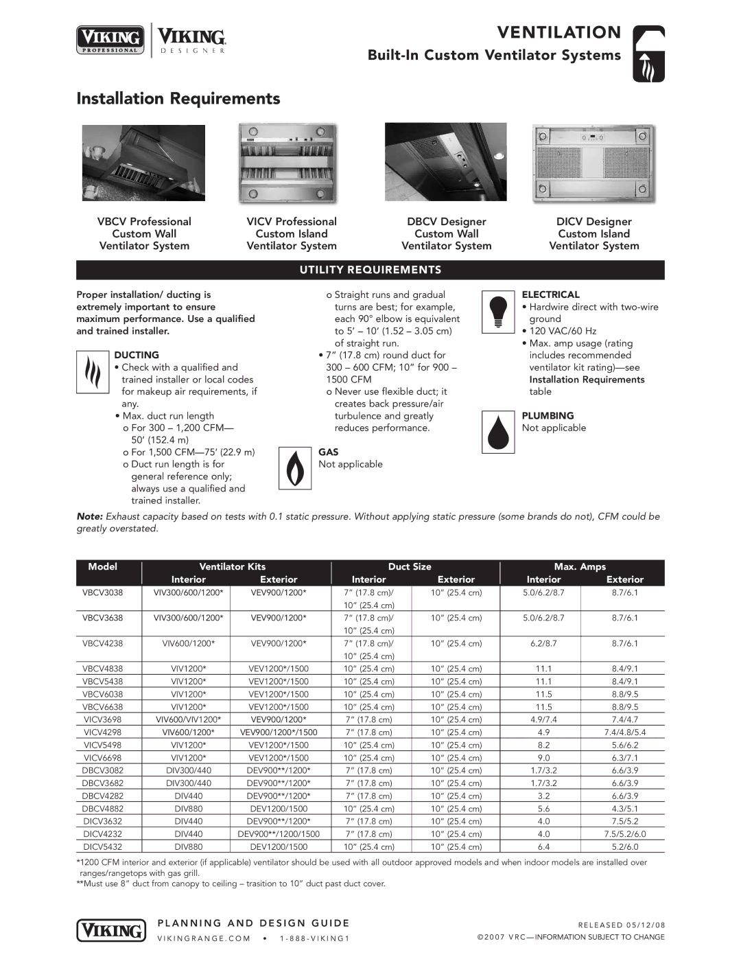
DBCV, VICV, DICV, VBCV specifications
Viking DICV (Differential Integrated Control Valve) is a significant advancement in control valve technology, designed to enhance precision in flow regulation across various industries. One of its main features is the differential control mechanism that allows for superior responsiveness to changes in flow dynamics. This results in improved process efficiency and reduced energy consumption. The DICV employs advanced materials and coatings, ensuring durability and resistance to wear even in harsh environments.Viking VICV (Vortex Induced Control Valve) is another innovative solution from the Viking range, aimed at optimizing control systems. VICV utilizes vortex-induced principles to facilitate enhanced control over liquid and gas flows. One standout feature is its ability to manage turbulent flow conditions effectively, which tends to be a challenge in traditional control valves. Technologies like smart actuators can be integrated with VICV, allowing for real-time monitoring and adaptive control strategies to optimize performance further.
Viking DBCV (Dynamic Balance Control Valve) boasts a unique design that addresses balance issues commonly faced in flow systems. Its dynamic balance technology effectively compensates for varying pressure conditions, leading to stable performance throughout different operational scenarios. This makes DBCV particularly suitable for applications requiring consistent flow rates, such as in chemical processing and water treatment plants. Moreover, the valve's maintenance-friendly design reduces downtime and operational costs.
Viking VBCV (Variable Bypass Control Valve) is tailored for systems that require adjustable flow rates based on demand. One of its key features is the ability to dynamically adjust its opening based on feedback from the system, ensuring optimal flow without unnecessary pressure losses. The incorporation of smart sensor technologies allows VBCV to work seamlessly with advanced control systems, offering better process control. Its rugged construction means it is well-suited for industrial applications, where conditions can be extreme.
In summary, the Viking DICV, VICV, DBCV, and VBCV represent a suite of advanced control valve technologies that address key challenges in fluid dynamics management. Each model has unique features that cater to specific application needs, prioritizing efficiency, durability, and precision. With ongoing advancements in materials and technologies, these valves are set to play a vital role in the future of automation and process control.

