VP-8258 Plus Smart Dock Installation Guide
Hardware
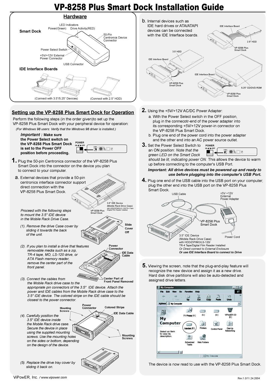
| LED Indicators |
Smart Dock | Power(Green) Drive Activity(RED) |
|
Power Select Switch ![]()
![]()
![]()
![]()
![]()
+5V/+12V External
Power Connector
USB Connector
IDE Interface Boards
(Connect with 3.5"/5.25" Devices) | (Connect with 2.5" HDD) |
Setting up the VP-8258 Plus Smart Dock for Operation
Perform the following steps (in the order given)to set up the
(For WIndows 98 users: Verify that the Windows 98 driver is installed.)
Important : Make sure the Power Select switch on
the | POWER |
|
|
ON OFF | +12V |
| |
is set to the Power OFF | POWER |
| |
|
|
| |
| ON OFF | Ext. | USB |
|
| +5V |
|
position before proceeding. |
|
|
|
1. Plug the
to connect to your computer.
a. External devices that provide a
direct connection with the
Proceed with the following steps |
| with |
/Digital Film Reader Installed | ||
| ||
to mount the 3.5" IDE device | Smart Dock |
|
|
| |
in the Mobile Rack Drive Case. |
|
|
(1). Remove the drive Case cover by |
| Slide |
| Cover | |
sliding it towards the back |
| |
| Off | |
of the unit. |
| |
|
| |
(2). If you plan to install a drive that features |
| Power |
removable media such as a zip, |
| Connector |
| IDE Data | |
| ||
| Cable | |
ATA Flash memory reader, |
|
|
remove the center part of the |
|
|
front panel. |
|
|
(3). Connect the cables from ![]() the Mobile Rack drive case to the
the Mobile Rack drive case to the
appropriate pin connectors of the 3.5" IDE device. Attach the power and IDE cables from the Mobile Rack drive case to the 3.5" IDE device. The colored stripe on the IDE cable should be closest to the power connector.
IDE Interface Board
2.5" HDD
Smart Dock
5.25"
a. With the Power Select switch in the OFF position, plug in the
b. Plug one end of the power cord into the power adapter and the other end into an AC power source outlet.
3. Set the Power Select Switch to | POWER |
|
|
|
| ||||
ON OFF |
|
|
|
| |||||
an ON position: Note that the |
|
|
|
| |||||
|
|
|
| POWER |
|
|
| ||
|
|
|
| ON | OFF | Ext. | USB | ||
|
|
|
|
|
| +5V | |||
green LED on the Smart Dock |
|
|
|
|
|
| +12V |
|
|
|
|
|
|
|
|
|
|
| |
|
|
|
|
|
|
|
|
| |
should be lit, indicating power ON. This allows the device to warm | |||||||||
up before connecting to the computer's USB Port. |
|
|
| ||||||
Important: All drive devices must be powered up and ready to use before plugging into the computer's USB Port.
4. Plug one end of the USB cable into the USB port on your computer; plug the other end into the USB port on the
Smart Dock.
USB Cable | +5V +12V |
| External |
| Power Adapter |

VP-8258 Plus
Smart Dock
3.5" IDE Device | Power Cord | |
(Mobile Rack Drive Case) | ||
|
with
Or Direct connect to External Enclosure
Or use IDE Interface Board to connect to Drive
5. Viewing the screen, note that the
recognize the new device and assign it as a new drive. Hard disk drive partitions will also be
My Computer
File Edit View Go Favorites | Help |
|
|
|
Up | Cut | Copy | Paste | Undo |
Power
Mounting Connector
Screws
(4). Carefully position the 3.5" IDE device inside ![]()
![]() the Mobile Rack drive case. Secure the device in place
the Mobile Rack drive case. Secure the device in place ![]() using the supplied mounting screws. Use the mounting holes
using the supplied mounting screws. Use the mounting holes
on the sides or bottom, depending on the design of the device.
(5). Replace the drive tray cover by sliding it back on.
Colored Stripe
IDE Data Cable
Mounting
Screws
Address | My Computer |
|
|
|
| 312 Floppy〔A:〕 | 〔C:〕 | 〔D:〕 | ViPowER CD |
|
|
|
| 〔E:〕 |
| 〕 | Printers | Control Panel | |
| Usbdisk〔F: |
| ||
Select an item |
|
| Networking | |
to view its |
|
|
|
|
description. |
|
|
| |
| Scheduled | Web Folders |
|
|
| Tasks |
|
|
|
The device is now read to use with the
ViPowER, Inc. / www.vipower.com | Rev.1.0/11.24.2004 |