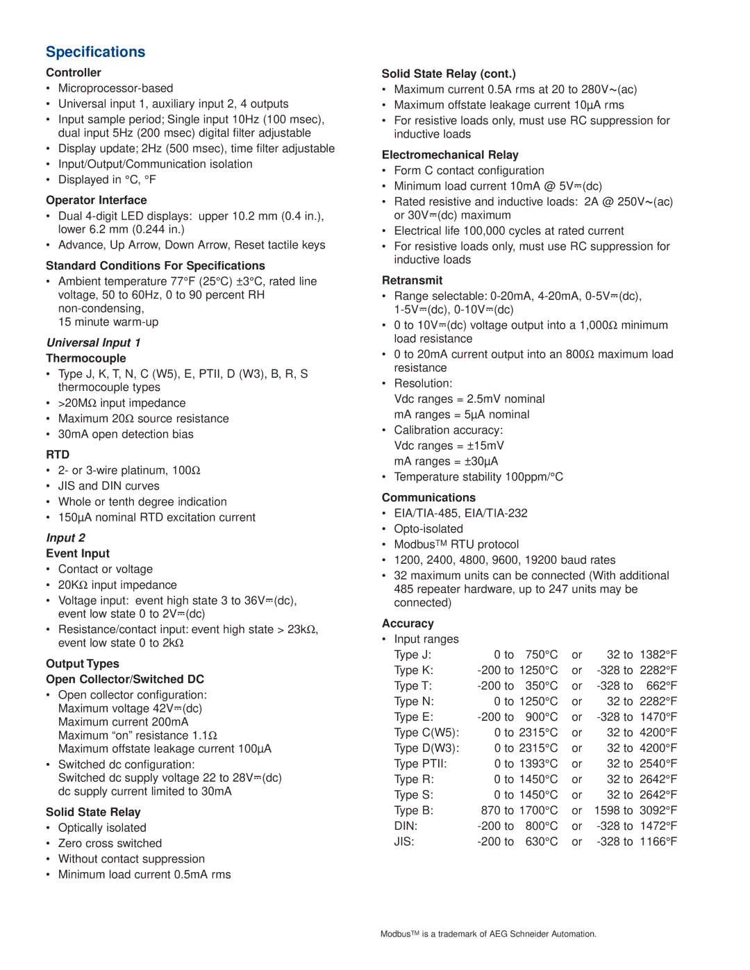
Series 97 specifications
The Watlow Electric Series 97 is a versatile and innovative temperature controller designed for a wide range of industrial applications. Renowned for its reliability and performance, the Series 97 comes equipped with several features and technologies that set it apart in the competitive landscape of industrial temperature control.One of the standout characteristics of the Series 97 is its advanced PID (Proportional-Integral-Derivative) control algorithm. This technology ensures precise temperature regulation, reducing overshoot and achieving stable temperature profiles. With its user-friendly interface, operators can easily configure the controller to meet specific application needs, making production processes more efficient.
The Series 97 is also built with a robust and durable design, suitable for harsh industrial environments. Its enclosure is rated for NEMA 4X, providing protection against dust, water, and corrosive elements. This makes it an ideal choice for applications ranging from food processing to chemical manufacturing, where reliability is crucial.
In addition to its rugged build, the Series 97 features a range of communication options, including Ethernet, RS-232, and RS-485 capabilities. This allows for integration into existing control systems and facilitates remote monitoring and data collection. The ability to communicate with other devices enhances the flexibility of temperature control strategies, making the Series 97 a valuable asset in any automated environment.
Furthermore, the controller supports multiple input types, including RTD, thermocouple, and analog inputs. This versatility allows users to customize the controller for various sensors, enhancing its applicability across different processes. The Series 97 can also be configured to manage multiple zones, increasing its functionality in complex systems.
The controller's intuitive graphical user interface comes with customizable displays and alarm configurations, allowing operators to set up convenient monitoring and alerts for any deviations from set parameters. This contributes to improved process safety and operational efficiency.
Overall, the Watlow Electric Series 97 temperature controller stands out for its precision, durability, and versatility in industrial temperature management. Its advanced features, combined with a user-friendly design, make it a preferred choice for professionals seeking reliable control solutions in demanding industrial environments. Whether for heating, cooling, or process control, the Series 97 is engineered to meet the rigorous demands of modern manufacturing.

