7 UPPER CHUTE (See Fig. 7A and 7B)
1.Lower mower to its lowest cutting position.
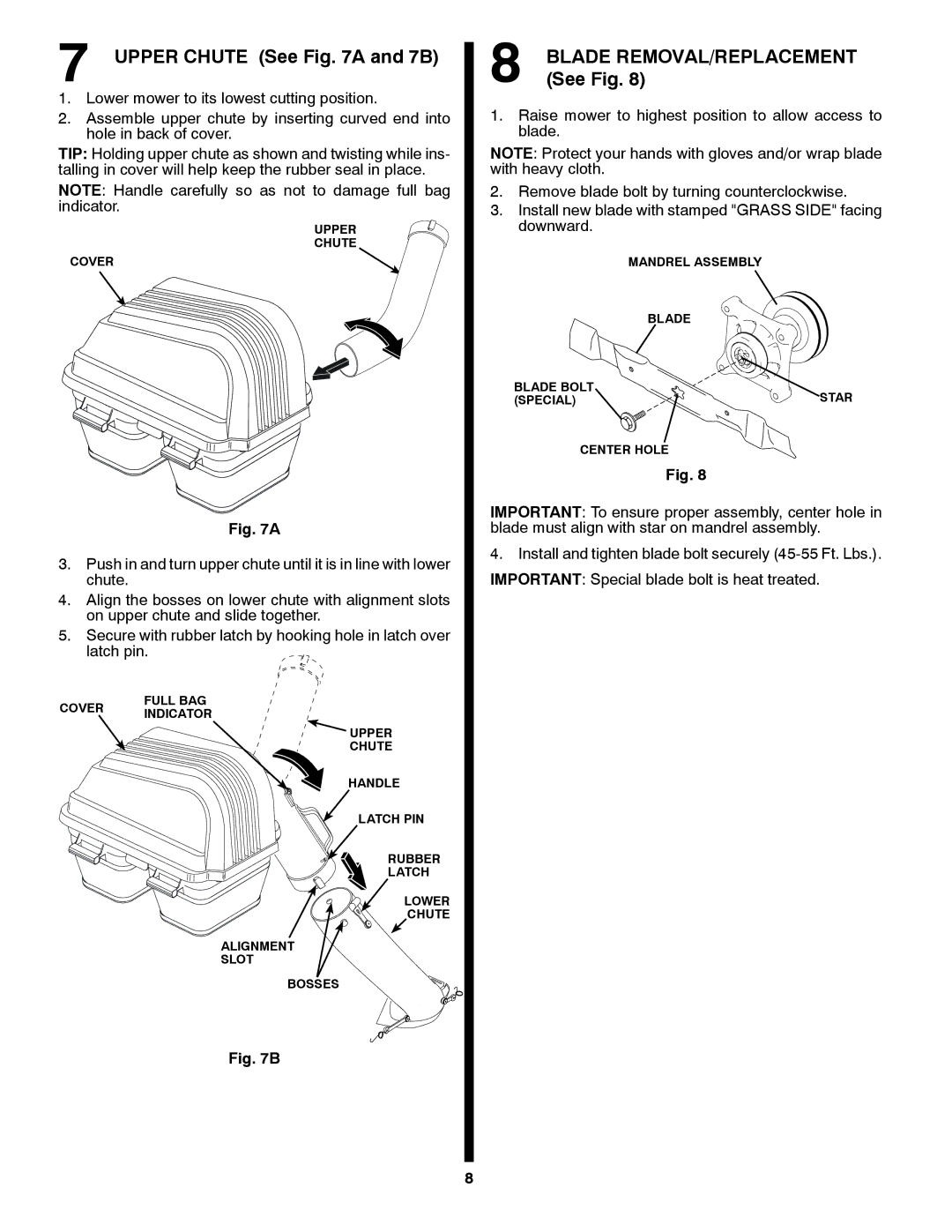
2.Assemble upper chute by inserting curved end into hole in back of cover.
TIP: Holding upper chute as shown and twisting while ins- talling in cover will help keep the rubber seal in place.
NOTE: Handle carefully so as not to damage full bag indicator.
UPPER
CHUTE
COVER
WARNING
WARNING
Fig. 7A
3.Push in and turn upper chute until it is in line with lower chute.
4.Align the bosses on lower chute with alignment slots on upper chute and slide together.
5.Secure with rubber latch by hooking hole in latch over
latch pin.
8 BLADE REMOVAL/REPLACEMENT (See Fig. 8)
1.Raise mower to highest position to allow access to blade.
NOTE: Protect your hands with gloves and/or wrap blade with heavy cloth.
2.Remove blade bolt by turning counterclockwise.
3.Install new blade with stamped "GRASS SIDE" facing downward.
| MANDREL ASSEMBLY |
| BLADE |
BLADE BOLT | STAR |
(SPECIAL) |
CENTER HOLE
Fig. 8
IMPORTANT: To ensure proper assembly, center hole in blade must align with star on mandrel assembly.
4.Install and tighten blade bolt securely
COVER | FULL BAG | |
INDICATOR | ||
|
WARNING
WARNING
![]() UPPER
UPPER
CHUTE
HANDLE
LATCH PIN
RUBBER
LATCH
LOWER
CHUTE
ALIGNMENT
SLOT
BOSSES
Fig. 7B
8