SERVICE AND ADJUSTMENTS
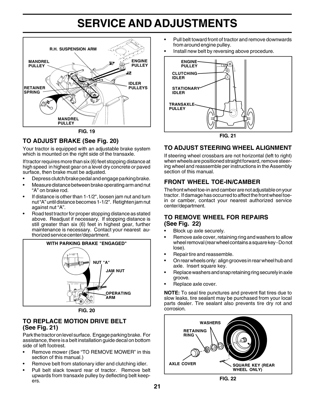
| R.H. SUSPENSION ARM |
MANDREL | ENGINE |
PULLEY | PULLEY |
| IDLER |
RETAINER | PULLEYS |
SPRING |
|
| MANDREL |
| PULLEY |
FIG. 19
TO ADJUST BRAKE (See Fig. 20)
Your tractor is equipped with an adjustable brake system which is mounted on the right side of the transaxle.
If tractor requires more than six (6) feet stopping distance at high speed in highest gear on a level dry concrete or paved surface, then brake must be adjusted.
•Depress clutch/brake pedal and engage parking brake.
•Measure distance between brake operating arm and nut “A” on brake rod.
•If distance is other than
•Road test tractor for proper stopping distance as stated above. Readjust if necessary. If stopping distance is still greater than six (6) feet in highest gear, further maintenance is necessary. Contact your nearest au- thorized service center/department.
WITH PARKING BRAKE "ENGAGED"
NUT "A"
JAM NUT
OPERATING
ARM
FIG. 20
TO REPLACE MOTION DRIVE BELT (See Fig. 21)
Park the tractor on level surface. Engage parking brake. For assistance, there is a belt installation guide decal on bottom side of left footrest.
•Remove mower (See “TO REMOVE MOWER” in this section of this manual.)
•Remove belt from stationary idler and clutching idler.
•Pull belt slack toward rear of tractor. Remove belt upwards from transaxle pulley by deflecting belt keep- ers.
•Pull belt toward front of tractor and remove downwards from around engine pulley.
•Install new belt by reversing above procedure.
ENGINE
PULLEY
CLUTCHING
IDLER
STATIONARY
IDLER
TRANSAXLE
PULLEY
FIG. 21
TO ADJUST STEERING WHEEL ALIGNMENT
If steering wheel crossbars are not horizontal (left to right) when wheels are positioned straight forward, remove steer- ing wheel and reassemble per instructions in the Assembly section of this manual.
FRONT WHEEL TOE-IN/CAMBER
The front wheel
TO REMOVE WHEEL FOR REPAIRS (See Fig. 22)
•Block up axle securely.
•Remove axle cover, retaining ring and washers to allow wheel removal (rear wheel contains a square key - Do not lose).
•Repair tire and reassemble.
•On rear wheels only: align grooves in rear wheel hub and axle. Insert square key.
•Replace washers and snap retaining ring securely in axle groove.
•Replace axle cover.
NOTE: To seal tire punctures and prevent flat tires due to slow leaks, tire sealant may be purchased from your local parts dealer. Tire sealant also prevents tire dry rot and corrosion.
WASHERS
RETAINING
RING
AXLE COVER | SQUARE KEY (REAR |
| |
| WHEEL ONLY) |
FIG. 22
21