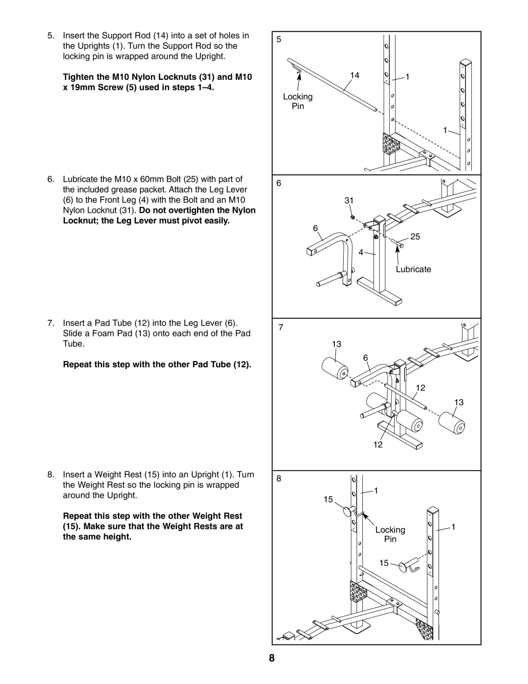
5. Insert the Support Rod (14) into a set of holes in | 5 |
|
|
the Uprights (1). Turn the Support Rod so the |
|
| |
|
|
| |
locking pin is wrapped around the Upright. |
|
|
|
Tighten the M10 Nylon Locknuts (31) and M10 | 14 | 1 |
|
x 19mm Screw (5) used in steps | Locking |
|
|
|
|
| |
| Pin |
|
|
|
|
| 1 |
6. Lubricate the M10 x 60mm Bolt (25) with part of | 6 |
|
|
the included grease packet. Attach the Leg Lever |
|
| |
|
|
| |
(6) to the Front Leg (4) with the Bolt and an M10 | 31 |
|
|
Nylon Locknut (31). Do not overtighten the Nylon |
|
|
|
Locknut; the Leg Lever must pivot easily. | 6 |
|
|
| 25 |
| |
|
|
| |
| 4 |
|
|
|
| Lubricate |
|
7. Insert a Pad Tube (12) into the Leg Lever (6). | 7 |
|
|
Slide a Foam Pad (13) onto each end of the Pad |
|
| |
|
|
| |
Tube. | 13 |
|
|
Repeat this step with the other Pad Tube (12). | 6 |
|
|
|
|
| |
|
| 12 |
|
|
|
| 13 |
|
| 12 |
|
8. Insert a Weight Rest (15) into an Upright (1). Turn | 8 |
|
|
the Weight Rest so the locking pin is wrapped |
|
| |
| 1 |
| |
around the Upright. | 15 |
| |
|
| ||
|
|
| |
Repeat this step with the other Weight Rest |
|
|
|
(15). Make sure that the Weight Rests are at |
| Locking | 1 |
the same height. |
|
| |
| Pin |
| |
|
|
| |
|
| 15 |
|
| 8 |
|
|
