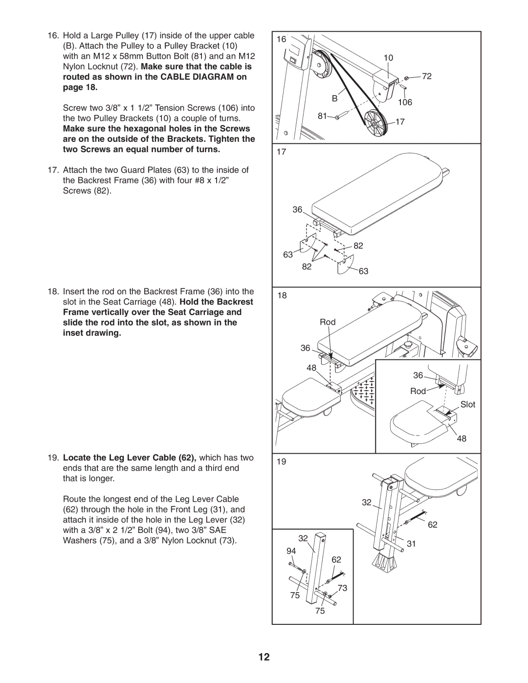
16.Hold a Large Pulley (17) inside of the upper cable
(B). Attach the Pulley to a Pulley Bracket (10) with an M12 x 58mm Button Bolt (81) and an M12 Nylon Locknut (72). Make sure that the cable is routed as shown in the CABLE DIAGRAM on page 18.
Screw two 3/8” x 1 1/2” Tension Screws (106) into the two Pulley Brackets (10) a couple of turns.
Make sure the hexagonal holes in the Screws are on the outside of the Brackets. Tighten the two Screws an equal number of turns.
17.Attach the two Guard Plates (63) to the inside of the Backrest Frame (36) with four #8 x 1/2” Screws (82).
18.Insert the rod on the Backrest Frame (36) into the slot in the Seat Carriage (48). Hold the Backrest
Frame vertically over the Seat Carriage and slide the rod into the slot, as shown in the inset drawing.
19.Locate the Leg Lever Cable (62), which has two ends that are the same length and a third end that is longer.
Route the longest end of the Leg Lever Cable (62) through the hole in the Front Leg (31), and attach it inside of the hole in the Leg Lever (32) with a 3/8” x 2 1/2” Bolt (94), two 3/8” SAE Washers (75), and a 3/8” Nylon Locknut (73).
16 |
| |
| 10 | |
| 72 | |
B | 106 | |
| ||
81 | 17 | |
| ||
17 |
| |
36 |
| |
63 | 82 | |
| ||
82 | 63 | |
| ||
18 |
| |
Rod |
| |
36 |
| |
48 | 36 | |
| ||
| Rod | |
| Slot | |
| 48 | |
19 |
| |
| 32 | |
| 62 | |
32 | 31 | |
94 | ||
| ||
62 |
| |
73 |
| |
75 |
| |
75 |
|
12
