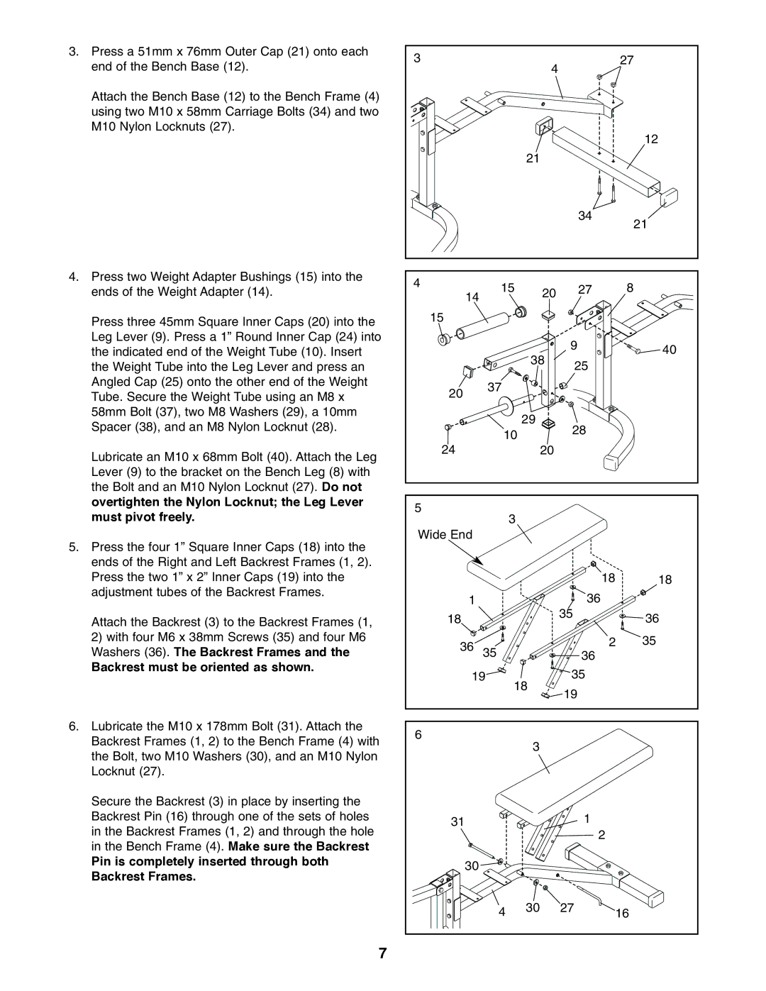
3.Press a 51mm x 76mm Outer Cap (21) onto each end of the Bench Base (12).
Attach the Bench Base (12) to the Bench Frame (4) using two M10 x 58mm Carriage Bolts (34) and two M10 Nylon Locknuts (27).
4.Press two Weight Adapter Bushings (15) into the ends of the Weight Adapter (14).
Press three 45mm Square Inner Caps (20) into the Leg Lever (9). Press a 1” Round Inner Cap (24) into the indicated end of the Weight Tube (10). Insert the Weight Tube into the Leg Lever and press an Angled Cap (25) onto the other end of the Weight Tube. Secure the Weight Tube using an M8 x 58mm Bolt (37), two M8 Washers (29), a 10mm Spacer (38), and an M8 Nylon Locknut (28).
Lubricate an M10 x 68mm Bolt (40). Attach the Leg Lever (9) to the bracket on the Bench Leg (8) with the Bolt and an M10 Nylon Locknut (27). Do not overtighten the Nylon Locknut; the Leg Lever must pivot freely.
5.Press the four 1” Square Inner Caps (18) into the ends of the Right and Left Backrest Frames (1, 2). Press the two 1” x 2” Inner Caps (19) into the adjustment tubes of the Backrest Frames.
Attach the Backrest (3) to the Backrest Frames (1, 2) with four M6 x 38mm Screws (35) and four M6 Washers (36). The Backrest Frames and the
Backrest must be oriented as shown.
6.Lubricate the M10 x 178mm Bolt (31). Attach the Backrest Frames (1, 2) to the Bench Frame (4) with the Bolt, two M10 Washers (30), and an M10 Nylon Locknut (27).
Secure the Backrest (3) in place by inserting the Backrest Pin (16) through one of the sets of holes in the Backrest Frames (1, 2) and through the hole in the Bench Frame (4). Make sure the Backrest
Pin is completely inserted through both Backrest Frames.
3 |
| 4 |
| 27 | |
|
|
|
| ||
|
|
|
| 12 | |
|
| 21 |
|
| |
|
|
| 34 | 21 | |
|
|
|
| ||
4 | 15 | 20 | 27 | 8 | |
14 | |||||
|
|
| |||
|
|
|
| ||
15 |
|
|
|
| |
|
|
| 9 | 40 | |
|
| 38 |
| ||
|
| 25 |
| ||
|
|
|
| ||
20 | 37 |
|
|
| |
|
|
|
| ||
|
| 29 | 28 |
| |
| 10 |
|
| ||
|
|
|
| ||
24 |
| 20 |
|
| |
5 | 3 |
|
|
| |
|
|
|
| ||
Wide End |
|
|
|
|
|
|
|
| 18 | 18 |
1 |
|
| 35 | 36 |
|
18 |
|
|
| 36 | |
|
|
|
| ||
36 | 35 |
|
| 2 | 35 |
|
| 36 |
| ||
19 | 18 | 35 |
| ||
|
| 19 |
|
| |
|
|
|
|
| |
6 |
| 3 |
|
|
|
|
|
|
|
| |
31 |
|
|
| 1 |
|
|
|
|
| 2 |
|
30 |
|
|
|
|
|
| 4 | 30 | 27 | 16 |
|
|
|
|
| ||
7
