Assembly
Before beginning assembly, carefully read the following information and instructions:
¥Place all parts of the weight bench in a cleared area and remove the packing materials; do not dispose of the packing materials until assembly is completed.
¥Read each assembly step before you begin.
¥For help identifying the small parts used in assembly, use the PART IDENTIFICATION CHART on the previous page. Note: Some small parts may have been
¥Tighten all parts as you assemble them, unless instructed to do otherwise.
¥As you assemble the weight bench, make sure that all parts are oriented as shown in the draw- ings.
THE FOLLOWING TOOLS (NOT INCLUDED) ARE REQUIRED FOR ASSEMBLY:
¥Two (2) adjustable wrenches ![]()
¥One (1) phillips screwdriver ![]()
¥One (1) rubber mallet ![]()
![]()
¥Lubricant, such as grease or petroleum jelly, and soapy water will also be needed.
Assembly will be more convenient if you have the following tools: A socket set, a set of
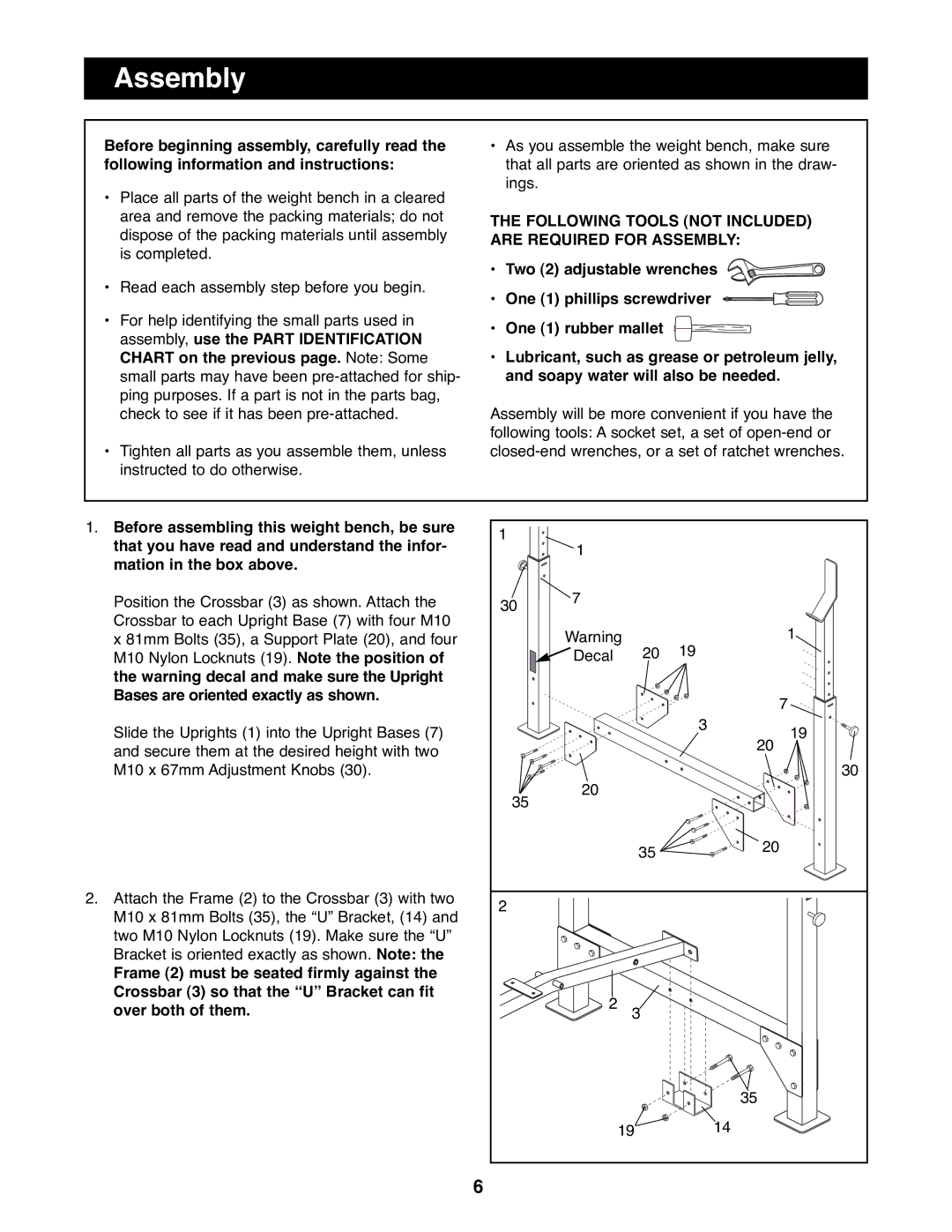
1. Before assembling this weight bench, be sure | 1 |
|
|
|
|
that you have read and understand the infor- | 1 |
|
|
| |
|
|
|
| ||
mation in the box above. |
|
|
|
|
|
Position the Crossbar (3) as shown. Attach the | 30 | 7 |
|
|
|
Crossbar to each Upright Base (7) with four M10 |
| Warning |
| 1 | |
x 81mm Bolts (35), a Support Plate (20), and four |
| 19 | |||
M10 Nylon Locknuts (19). Note the position of |
| Decal | 20 |
| |
the warning decal and make sure the Upright |
|
|
|
|
|
Bases are oriented exactly as shown. |
|
|
|
| 7 |
|
|
|
|
| |
Slide the Uprights (1) into the Upright Bases (7) |
|
|
| 3 | 19 |
|
|
|
| ||
and secure them at the desired height with two |
|
|
|
| 20 |
|
|
|
|
| |
M10 x 67mm Adjustment Knobs (30). |
|
|
|
| 30 |
| 35 | 20 |
|
|
|
|
|
|
|
| |
|
|
| 35 |
| 20 |
|
|
|
|
| |
2. Attach the Frame (2) to the Crossbar (3) with two | 2 |
|
|
|
|
M10 x 81mm Bolts (35), the ÒUÓ Bracket, (14) and |
|
|
|
| |
|
|
|
|
| |
two M10 Nylon Locknuts (19). Make sure the ÒUÓ |
|
|
|
|
|
Bracket is oriented exactly as shown. Note: the |
|
|
|
|
|
Frame (2) must be seated firmly against the |
|
|
|
|
|
Crossbar (3) so that the ÒUÓ Bracket can fit |
| 2 |
|
|
|
over both of them. |
| 3 |
|
| |
|
|
|
|
| 35 |
|
|
| 19 |
| 14 |
6