SPA JET OPERATION
B
| B | |
| C | |
A | E | |
D | ||
|
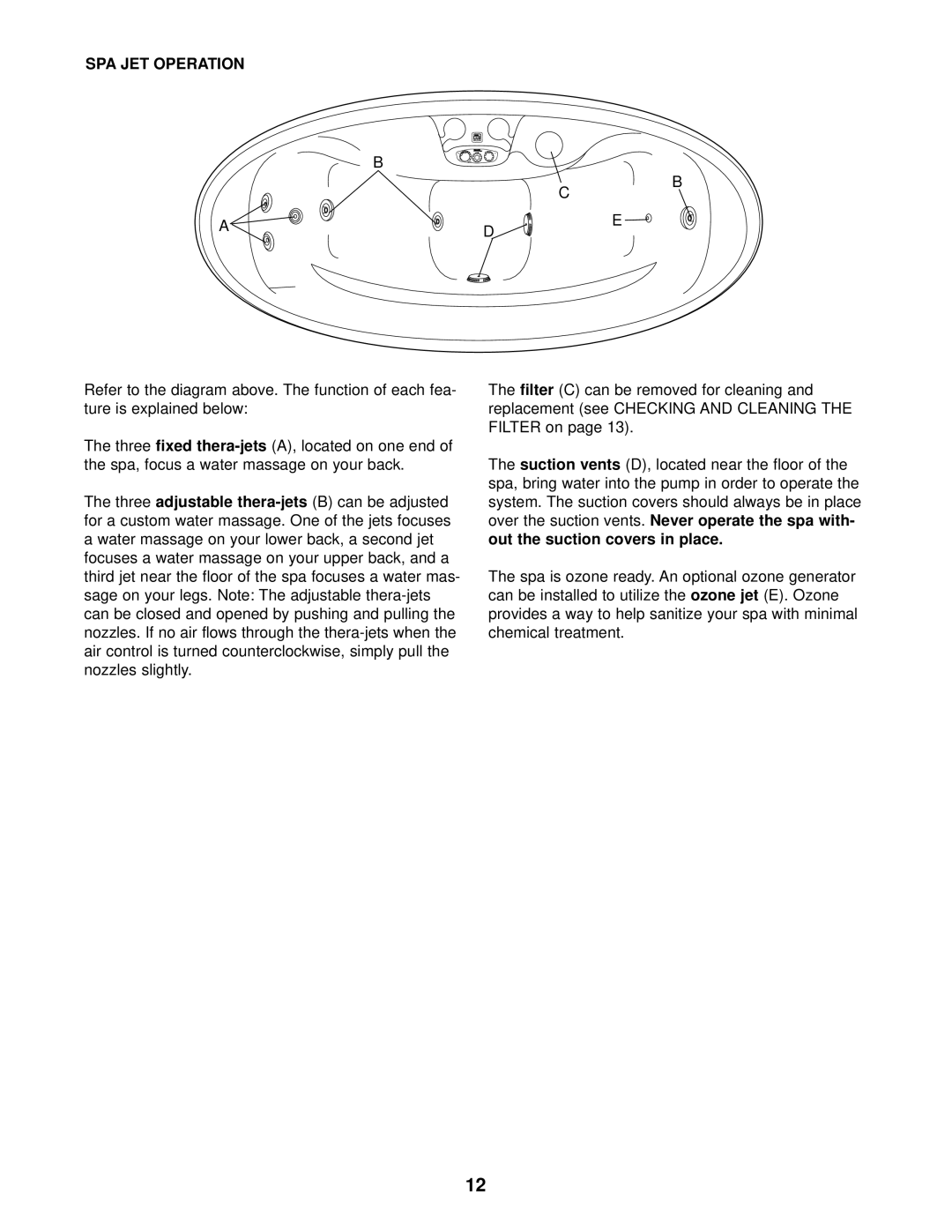
Refer to the diagram above. The function of each fea- ture is explained below:
The three fixed
The three adjustable
The filter (C) can be removed for cleaning and replacement (see CHECKING AND CLEANING THE FILTER on page 13).
The suction vents (D), located near the floor of the spa, bring water into the pump in order to operate the system. The suction covers should always be in place over the suction vents. Never operate the spa with- out the suction covers in place.
The spa is ozone ready. An optional ozone generator can be installed to utilize the ozone jet (E). Ozone provides a way to help sanitize your spa with minimal chemical treatment.
12
