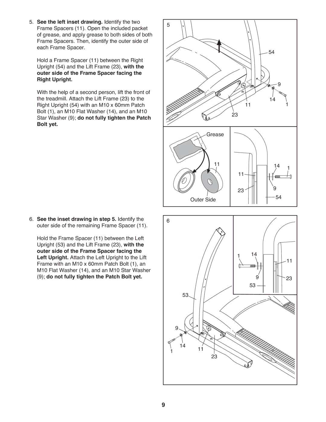
5. See the left inset drawing. Identify the two | 5 |
|
|
|
|
|
|
|
|
Frame Spacers (11). Open the included packet |
|
|
|
|
|
|
|
| |
of grease, and apply grease to both sides of both |
|
|
|
|
|
|
|
|
|
Frame Spacers. Then, identify the outer side of |
|
|
|
|
|
|
|
|
|
each Frame Spacer. |
|
|
|
|
|
|
| 54 |
|
Hold a Frame Spacer (11) between the Right |
|
|
|
|
|
|
|
| |
Upright (54) and the Lift Frame (23), with the |
|
|
|
|
|
|
|
|
|
outer side of the Frame Spacer facing the |
|
|
|
|
|
|
|
|
|
Right Upright. |
|
|
|
|
|
|
| 9 |
|
With the help of a second person, lift the front of |
|
|
|
|
|
|
|
| |
the treadmill. Attach the Lift Frame (23) to the |
|
|
|
|
| 11 |
| 14 | 1 |
Right Upright (54) with an M10 x 60mm Patch |
|
|
|
|
|
|
| ||
Bolt (1), an M10 Flat Washer (14), and an M10 |
|
|
|
| 23 |
|
|
|
|
Star Washer (9); do not fully tighten the Patch |
|
|
|
|
|
|
|
| |
Bolt yet. |
|
|
| Grease |
|
|
|
|
|
|
|
|
|
|
|
|
|
| |
|
|
|
| 11 | 11 |
|
| 14 | 1 |
|
|
|
|
|
|
| 9 |
| |
|
|
| Outer Side | 23 |
|
|
| ||
|
|
|
|
|
| 54 |
| ||
6. See the inset drawing in step 5. Identify the | 6 |
|
|
|
|
|
|
|
|
outer side of the remaining Frame Spacer (11). |
|
|
|
|
|
|
|
| |
Hold the Frame Spacer (11) between the Left |
|
|
|
|
|
|
|
|
|
Upright (53) and the Lift Frame (23), with the |
|
|
|
|
|
|
|
|
|
outer side of the Frame Spacer facing the |
|
|
|
| 1 | 14 |
|
| |
Left Upright. Attach the Left Upright to the Lift |
|
|
|
|
| 11 | |||
Frame with an M10 x 60mm Patch Bolt (1), an |
|
|
|
|
|
|
|
| |
M10 Flat Washer (14), and an M10 Star Washer |
|
|
|
|
|
| 9 |
| 23 |
(9); do not fully tighten the Patch Bolt yet. |
| 53 |
|
|
| 53 |
| ||
|
|
|
|
|
|
|
| ||
|
|
|
|
|
|
|
|
| |
|
| 9 |
|
|
|
|
|
|
|
| 1 | 14 | 11 | 23 |
|
|
|
|
|
|
|
|
|
|
|
|
|
| |
| 9 |
|
|
|
|
|
|
|
|
