MA7200 PLUS Inverter 3 to 75 HP Fan Quick Start Manual
_______________________________________________________________
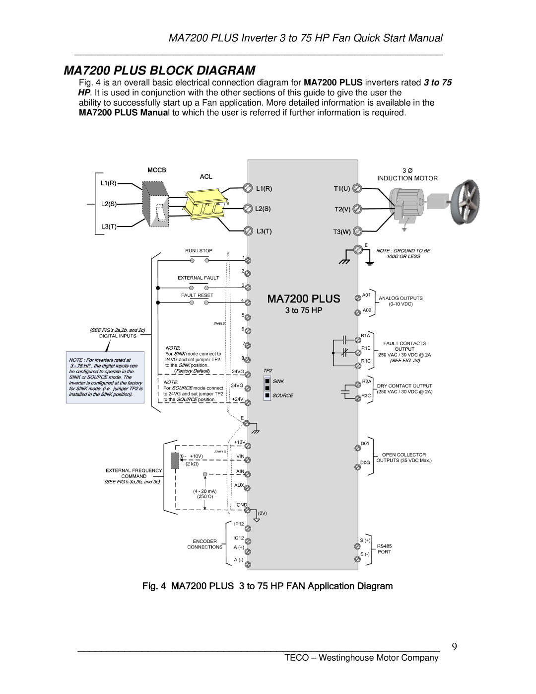
MA7200 PLUS BLOCK DIAGRAM
Fig. 4 is an overall basic electrical connection diagram for MA7200 PLUS inverters rated 3 to 75 HP. It is used in conjunction with the other sections of this guide to give the user the
ability to successfully start up a Fan application. More detailed information is available in the MA7200 PLUS Manual to which the user is referred if further information is required.
______________________________________________________________ 9