2.Remove
A![]()
![]()
CD
B
A. External ground conductor screw
B.Tab
C.Terminal block cover
D.
3.Assemble ³⁄₄"
![]() B
B
A ![]()
![]()
C
A. Strain relief clamp sections
B. Dryer cabinet
C. Strain relief screws
4.Complete installation following instructions for your type of electrical connection:
•
•
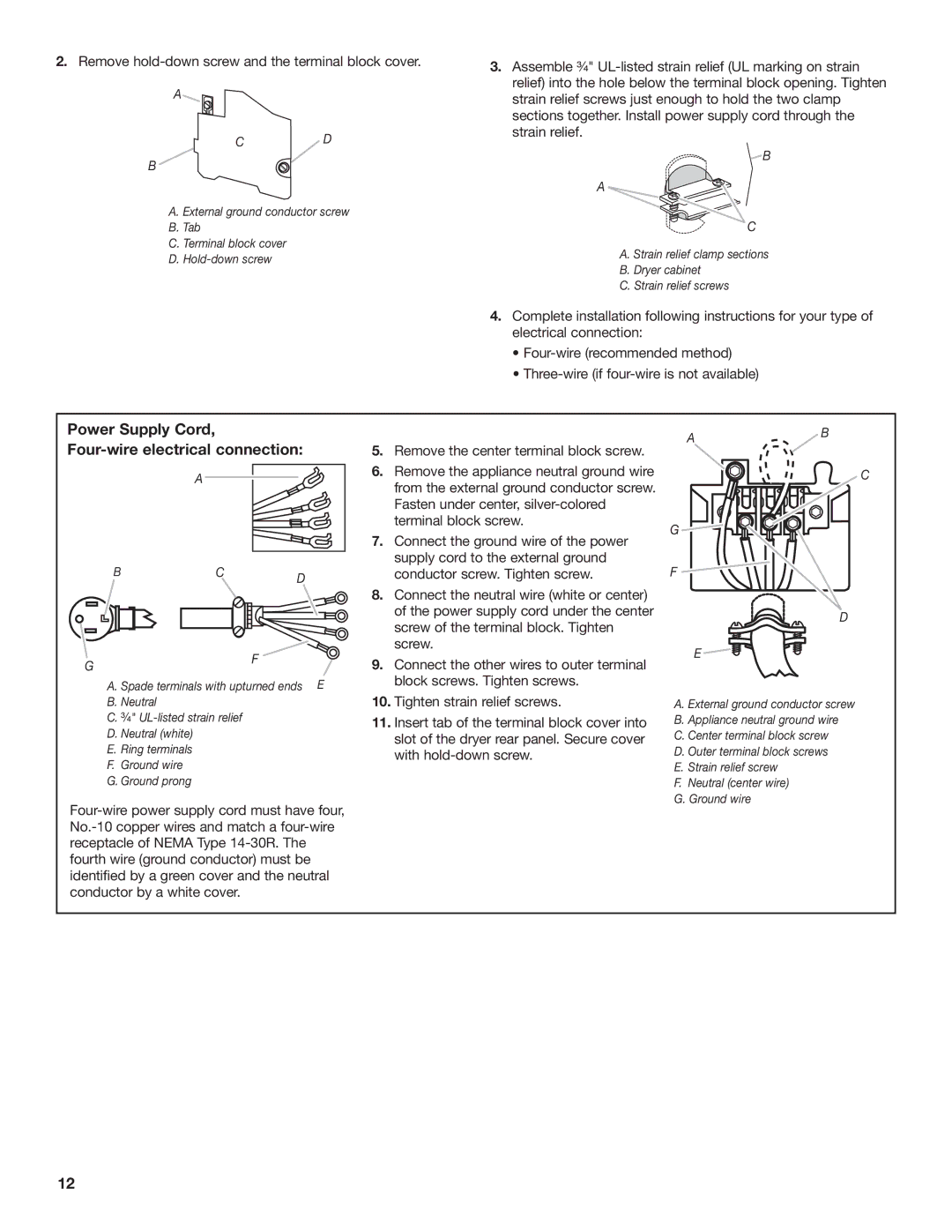
Power Supply Cord, Four-wire electrical connection:
| A |
|
B | C | D |
|
|
GF
A. Spade terminals with upturned ends E
B.Neutral
C.³⁄₄"
D.Neutral (white)
E.Ring terminals
F.Ground wire
G.Ground prong
5.Remove the center terminal block screw.
6.Remove the appliance neutral ground wire from the external ground conductor screw. Fasten under center,
7.Connect the ground wire of the power supply cord to the external ground conductor screw. Tighten screw.
8.Connect the neutral wire (white or center) of the power supply cord under the center screw of the terminal block. Tighten screw.
9.Connect the other wires to outer terminal block screws. Tighten screws.
10.Tighten strain relief screws.
11.Insert tab of the terminal block cover into slot of the dryer rear panel. Secure cover with
AB
C
G ![]()
F
D
E![]()
A.External ground conductor screw
B.Appliance neutral ground wire
C.Center terminal block screw
D.Outer terminal block screws
E.Strain relief screw
F.Neutral (center wire)
G.Ground wire
12