Manuals
/
Whirlpool
/
Kitchen Appliance
/
Refrigerator
Whirlpool
IC4
manual
Built-In Models SB, All Other Models, Operating Instructions
Models:
IC4
1
5
8
8
Download
8 pages
48.2 Kb
1
2
3
4
5
6
7
8
Warranty
Procedure
Safety
Page 5
Image 5
Page 4
Page 6
Page 5
Image 5
Page 4
Page 6
Contents
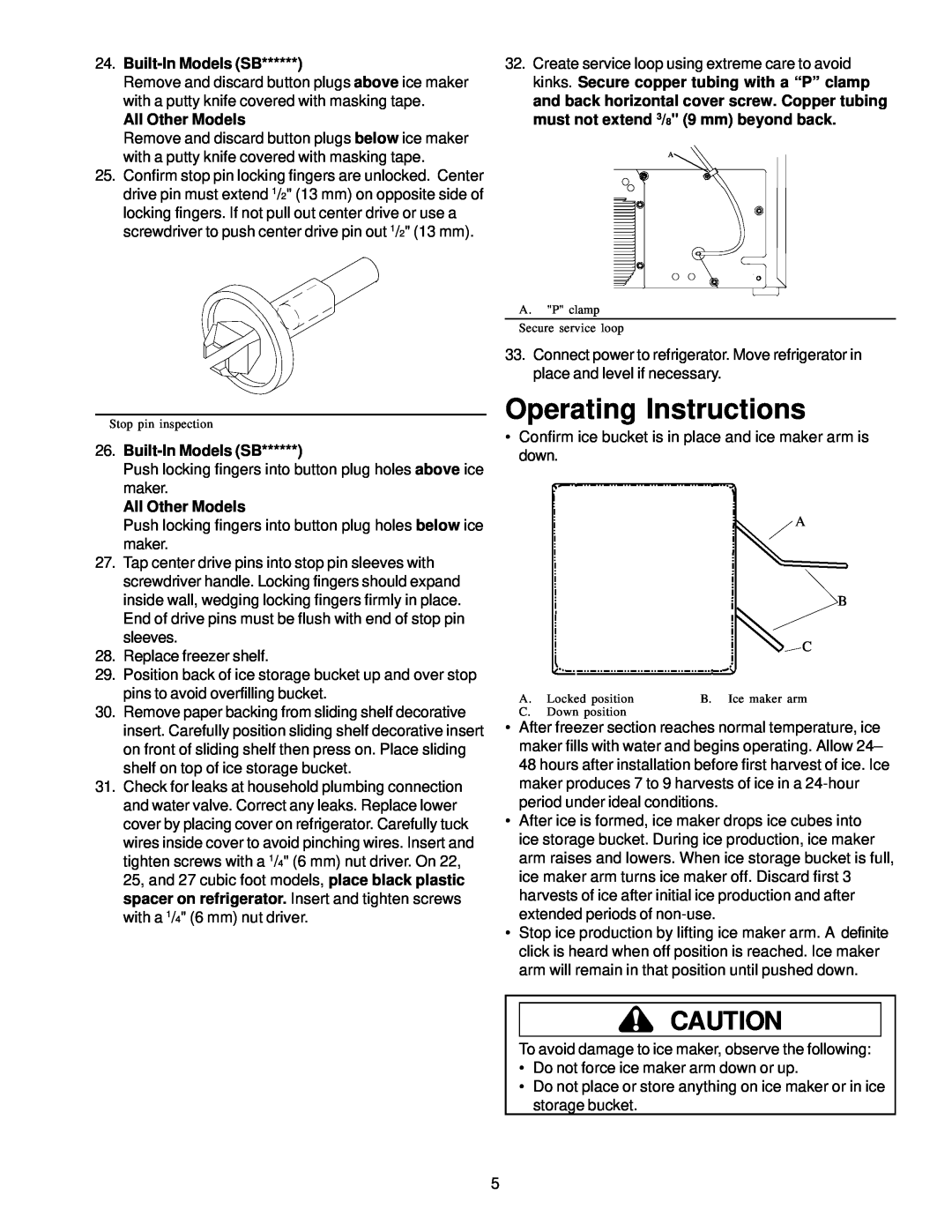
Operating Instructions
IC4 Side-by-Side Refrigerator Ice Maker Kit Installation and
Introduction
Safety Instructions
Parts
Tools Required
Materials Required
Procedure
16. Remove top freezer shelf
All Other Models
24. Built-In Models SB
26. Built-In Models SB
Operating Instructions
Warranty Ice Maker Full One Year Warranty
Before Calling For Service
Warranty Limitations
Warranty Is Void If
Page
Ó 1998 Amana Appliances
Amana, Iowa
Top
Page
Image
Contents