VENTED KITCWEhl RANGE HOOD FOR 120 V. OPERATION
KITCHEN
RANGE HOOD
MODEL
RH5336XL
READ AND SAVE THESE INSTRUCTIONS
Before you begin, read the following instructions
completely and carefully. If followed, they will simplify
the installation job.
IMPORTANT: OBSERVE ALL GOVERNING CODES AND ORDINANCES
SAVE THESE INSTRUCTIONS FOR THE LOCAL
ELECTRICAL INSPECTOR’S USE
2. Dependtng on mounting surface, use either prepunched holes In the hood flanges at the top or the mountrng brackets included with the hood to secure the hood to the furr down. lf
mounttng brackets are used, screw the brackets to the furr down SIX to none Inches from the hood ends. Use the center hole to mount the bracket tnitiallv. Leave the center screw loose enough to rotate on the center screw. Rotate the brackets as shown In Fig. 3, and lift the hood canopy (without black fan box assy.) into posrtion. Rotate brackets until they are supportlng
the hood canopy. Attach remaining screws
INSTALLING | DUCT | WORK: |
|
|
|
|
|
|
|
|
|
|
| 3. | Make |
| electrical |
| connectton |
| in | wiring |
| tunctlon | box | ||||||||||||
Figure |
|
| typical | installation. |
|
|
|
|
|
|
|
|
|
|
|
|
| ||||||||||||||||||||
1 shows | The | unit | vents | vertically |
| only | accordrng |
|
| to | the |
| latest |
| Natlonal | ElectrIcal | Code | and | |||||||||||||||||||
with | 3% X | 10 | duct. |
|
|
|
|
|
|
|
|
|
|
|
|
|
| applicable |
|
| local | codes. | Hood | must | be | permanently |
| grounded. |
| ||||||||
Use | Figure | 2 to cut duct | hole |
| and | wrrtng | entrance | hole | In | furr | 4. | Ltft | fan |
| box | assembly |
| into | position |
| and | make | necessary |
| |||||||||||||
down. | Note | control | side | for | hood | on | Fig. | 2. | be | sure | thus | IS the | ductwork |
| connectlons. |
| Secure |
| fan | box | assembly | to | hood | ||||||||||||||
same | side | as | the | cook | top controls. |
|
|
|
|
|
|
|
| canopy | with | SIX | screws. |
|
|
|
|
|
|
|
|
|
|
| |||||||||
Installation | under | kitchen | furr | down: |
|
|
|
|
|
|
|
| 5. | Replace |
| blower | 8 | filter. |
|
|
|
|
|
|
|
|
|
|
| ||||||||
1. | For | easy | installation |
| hood |
| should | be | drsassembled. |
| See fig. | NOTE: | It | has been | found | that | a large | part | of | the | energy | loss | of | ||||||||||||||
5. First | remove | aluminum |
| filter | from |
| fan | box | assembly | by | |||||||||||||||||||||||||||
pulling | tab | toward | opposrte | end | of filter. |
| Then | remove | blower | the | average |
| home | IS due to | outside | arr | infiltrating |
| the | structure. |
| ||||||||||||||||
assembly |
| by | unpluging | blower | power |
| leads | and | pushing | Seal | around |
| ductwork |
| where | it | passes | through | outside | walls | or | ||||||||||||||||
retatnlng | brackets | off | retaining |
| bumps. | Finally, | remove |
| black | ceiling. | Seal | around | electrlcal |
| wrrrng also |
|
|
|
|
|
| ||||||||||||||||
fan | box | assembly | by | removing |
| 6 screws. |
| (See fig. 6). Remove |
|
|
|
|
|
|
|
|
|
|
|
|
|
|
|
|
|
|
| ||||||||||
hood | mounting | brackets | from | interior | shipping | position. |
|
|
|
|
|
|
|
|
|
|
|
|
|
|
|
|
|
|
|
|
| ||||||||||
|
|
|
|
|
|
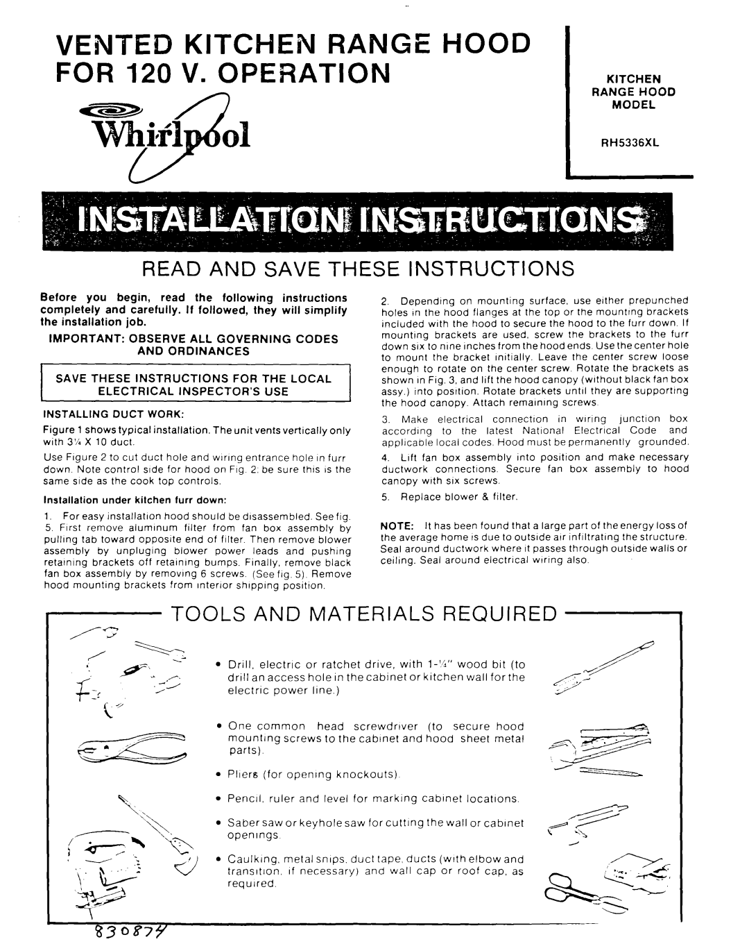
| TOOLS |
| AND | MATERIALS |
|
| REQUIRED |
|
|
|
|
|
|
|
| ||||||||||||||||
l
l
Drill, | electric | or ratchet | drive, | with | wood | bit | (to | |
drill an access | hole in the | cabinet | or | kitchen | wall | for | the | |
electric | power | line.) |
|
|
|
|
|
|
One common head screwdrtver (to secure hood
mOUntlng screws to the cabtnet and hood sheet metal parts).
l Plier& (for opening knockouts)
l Pencil, ruler and level for marklng cabinet locattons.
l Saber saw or keyhole saw for cutting the wall or cabinet opentngs
l Caulkrng. | metal snips. | duct tape, | ducts | (wrth | elbow | and | |
transttlon. | If necessary) | and wall | cap | or | roof | cap, | as |
required. |
|
|
|
|
|
|
|