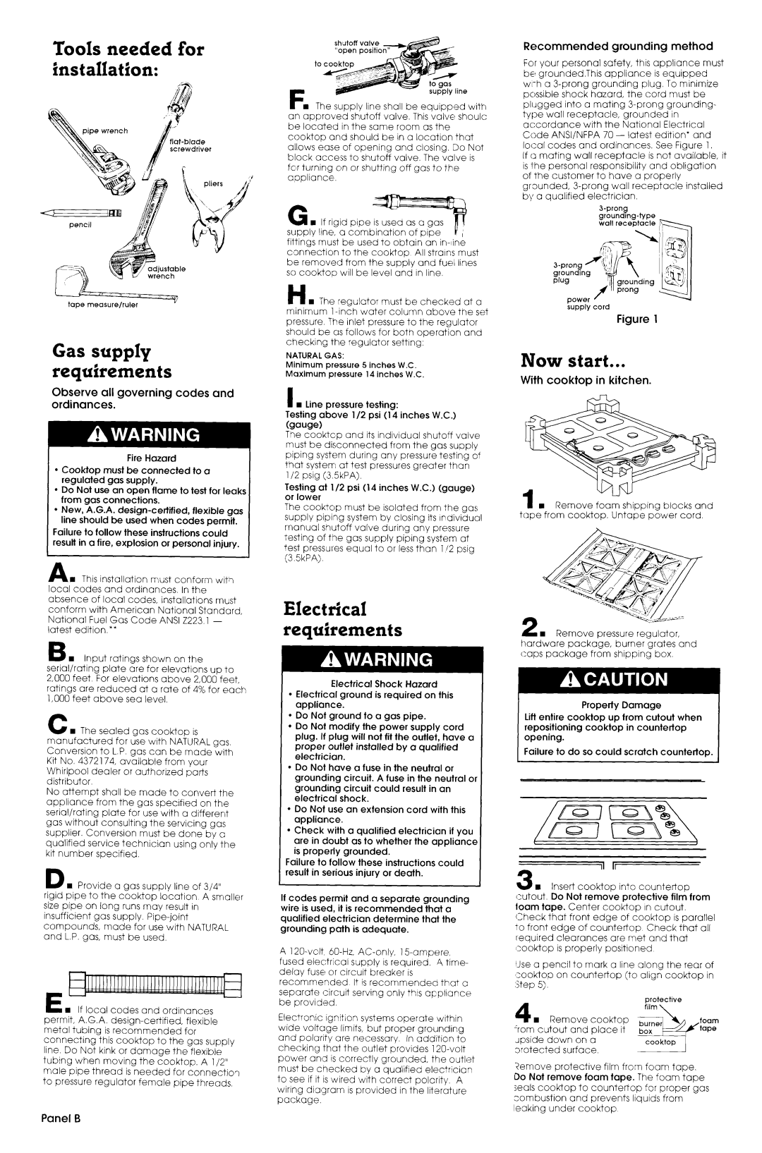
Tools needed for installation:
ipe wrench
’ adjustable !?” wrench
tape measure/ruler
Gas supply requirements
Observe all governing codes and ordinances.
Fire Hazard
l Cooktop must be connected to a regulated gas supply.
l Do Not use an open flame to test for leaks from gas connections.
l New, A.G.A.
Failure to follow these instructions could result in a fire, explosion or personal injury.
AA q This installation must conform with local codes and ordinances. In the absence of local codes, installations must conform with American National Standard, National Fuel Gas Code ANSI 2223.1 - latest edition.**
B n Input ratings shown on the serial/rating plate are for elevations up to 2,000 feet. For elevations above 2,000 feet, ratings are reduced at a rate of 4% for each 1,000 feet above sea level.
C w The sealed gas cooktop is
manufactured for use with NATURAL gas, Conversion to L.P. gas can be made with Kit No. 4372174, available from your Whirlpool dealer or authorized parts distributor.
No attempt shall be made to convert the appliance from the gas specified on the serial/rating plate for use with a different gas without consulting the servicing gas supplier. Conversion must be done by a qualified service technician using only the kit number specified.
D n Provide a gas supply line of 3/4”
rigid pipe to the cooktop location A smaller size pipe on long runs may result in insufficient gas supply.
E n If local codes and ordinances
permit, A.G.A.
metal tubing is recommended for connecting this cooktop to the gas supply line. Do Not kink or damage the flexible tubing when moving the cooktop. A l/2” male pipe thread is needed for connection to pressure regulator female pipe threads,
shutoff valve
F. The supply line shall be equipped with
an approvedshutoff valve. This v&e shoulc be located in the same room as the cooktop and should be in a location that allows ease of opening and closing. Do Not block acce’ss to shutoff valve. The valve is for turning on or shutting off gas to the appliance.
fittings must be used to obtain an
H n The regulator must be checked at a minimum
NATURAL GAS:
Minimum pressure 5 inches W.C.
Maximum pressure 14 inches W.C.
I n Line pressure testing:
Testing above l/2 psi (14 inches W.C.)
The cooktcp and its individual shutoff valve
must be disconnected from the gas supply pping system during any pressure testing of that system1 at test pressures greater than l/2 psig (3.5kPA).
Testing at l/2 psi (14 inches W.C.) (gauge) or lower
The cooktop must be isolated from the gas supply piping system by closing its rrdividual manual shutoff valve during any pressure testing of tl?e gas supply piping system at test pressures equal to or less than l/2 psig (3.5kPA).
Electrical requirements
Electrical Shock Hazard
l Electrical ground is required on this appliance.
l Do Not ground to a gas pipe.
l Do Not modify the power supply cord plug. If plug will not fit the outlet, have a proper outlet installed by a qualified electrician.
l Do Not have a fuse in the neutral or grounding circuit. A fuse in the neutral o grounding circuit could result in an electrical shock.
l Do Not use an extension cord with this appliance.
l Check with a qualified electrician if you are in doubt as to whether the appliance is properly grounded.
Failure to follow these instructions could result in serious injury or death.
If codes permit and a separate grounding
wire is used, it is recommended that a qualified electrician determine that the grounding path is adequate.
A 120~volt.
fused electrical supply is required. A time- delay fuse or circuit breaker is
recommended It is recommended that a separate circuit serving only this appliance be provided.
Electronic ignition systems operate within wide voltage limits, but proper grounding and polarity are necessary. In addition to checking that the outlet provides
Recommended grounding method
For your personal safety, this appliance must be grounded.This appliance is equipped
accordance with the National Electrical Code ANSI/NFPA 70 - latest edition* and local codes and ordinances. See Figure 1.
If a mating wall receptacle is not available, it is the personal responsibility and obligation
of the customer to have a properly
grounded,
supply cord
Figure 1
Now start...
With cooktop in kitchen.
u-
=Remove foam shipping blocks and tape from cooktop. Untape power cord
2 n Remove pressure regulator, hardware package, burner grates and caps package from shipping box.
Property Damage
Lift entire cooktop up from cutout when repositioning cooktop in countertop opening.
Failure to do so could scratch countertop.
tI
3 n Insert cooktop into countertop
cutout. Do Not remove protective film from loam tape. Center cooktop In cutout.
Check that front edge of cooktop is parallel
to front edge of countertop Check that all required clearances are met and that cooktop is properly positioned
IJse a pencil to mark a line along the rear of Icooktop on countertop (to align cooktop in :Step 5).
|
|
| protective | |
|
|
| ,.a | _ |
n | Remove | cooktop | foam | |
‘rom cutout | and | place it | tape | |
upside down | on | a |
| |
3rotected | surface. |
| ||
?emove protective film from foam tape. Do Not remove foam tape. The foam tape seals cooktop to countertop for proper gas combustion and prevents liquids from leaking under cooktop
Panel 6