
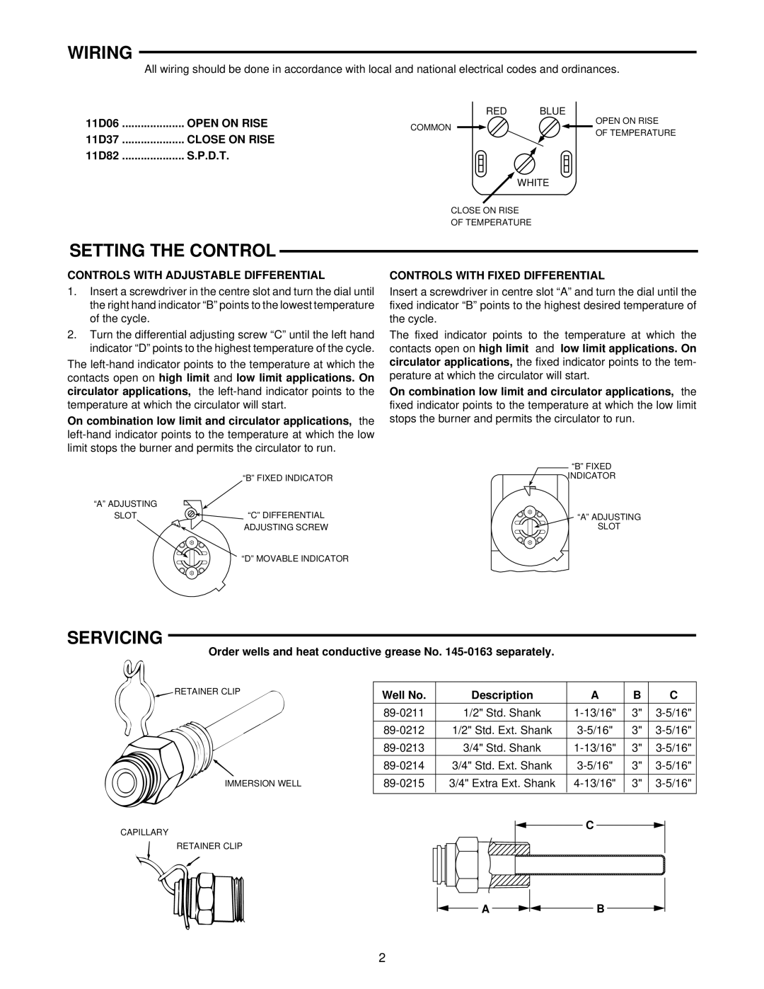
11D37, 11D82, 11D06 specifications
White Rodgers, a prominent name in HVAC control systems, has developed a range of thermostats designed to optimize heating and cooling efficiency in residential and commercial applications. Among their notable models are the 11D82, 11D06, and 11D37, each offering unique features and technologies that cater to diverse user needs.The White Rodgers 11D82 thermostat is renowned for its programmable capabilities, allowing users to set different temperature schedules throughout the week. With a user-friendly interface and intuitive touchscreen display, the 11D82 simplifies temperature adjustments and scheduling. This model also comes equipped with a 5-1-1 scheduling feature, enabling homeowners to customize weekday and weekend settings independently. The 11D82 utilizes advanced algorithms to maintain optimal temperature levels while promoting energy efficiency, which can lead to substantial cost savings on utility bills.
On the other hand, the 11D06 is designed with a more straightforward, non-programmable approach, making it ideal for users who prefer basic temperature control without the complexity of programming. The 11D06 features a sleek design and a digital display that clearly shows the current temperature, ensuring ease of use. This model is particularly suitable for environments where temperature settings change infrequently, delivering reliable performance with minimal user intervention.
The 11D37, meanwhile, is a versatile model that integrates advanced technologies such as the Auto Changeover feature, which automatically switches between heating and cooling as needed. This ensures optimal comfort in varying weather conditions without requiring manual adjustments. The 11D37 is also equipped with a user-friendly interface and a precise temperature control system, allowing for accurate temperature management. Additionally, its compatibility with multi-stage heating and cooling systems makes it a suitable choice for sophisticated HVAC setups.
All three models are designed with durability and reliability in mind, reflecting White Rodgers' commitment to quality. They incorporate features such as easy wiring configurations, compatibility with a variety of HVAC systems, and energy-saving technologies that enhance their overall efficiency.
In summary, the White Rodgers 11D82, 11D06, and 11D37 thermostats offer distinct advantages tailored to user preferences, from programmable features to simple, user-friendly designs. Each model showcases White Rodgers' dedication to providing innovative solutions that enhance climate control while promoting energy efficiency.