Cooling System
This thermostat has a
!CAUTION
To prevent compressor and/or property damage, if the outdoor temperature is below 50°F, DO NOT operate the cooling system.
1.Move SYSTEM switch to COOL position.
2.Press ![]() to adjust thermostat setting below room tempera- ture. The blower should come on immediately on high speed, followed by cold air circulation
to adjust thermostat setting below room tempera- ture. The blower should come on immediately on high speed, followed by cold air circulation
3.Press ![]() to adjust temperature setting above room tem- perature. The cooling system should stop operating.
to adjust temperature setting above room tem- perature. The cooling system should stop operating.
Before you begin programming your thermostat, you should be familiar with its features and with the display and the location and operation of the thermostat buttons. Your thermostat consists of two parts: the thermostat cover and the base. To remove the cover, gently pull it straight out from the base. To replace the cover, line up the cover with the base and press gently until the cover snaps onto the base.
THE THERMOSTAT BASE
Other than ![]() and
and ![]() , the following buttons and switches are
, the following buttons and switches are
located behind the door on the bottom of the thermostat cover (see fig. 11). Pull the door down to open it.
The Thermostat Buttons and Switches
OPERATION
1 | 2 |
| SET TIME VIEW PRGM RUN PRGM HOLD TEMP | FAN ON AUTO COOL OFF HEAT | |||||
|
|
|
|
|
|
|
|
|
|
|
|
|
|
|
|
|
|
|
|
|
|
|
|
|
|
|
|
|
|
|
|
|
|
|
|
|
|
|
|
|
|
|
|
|
|
|
|
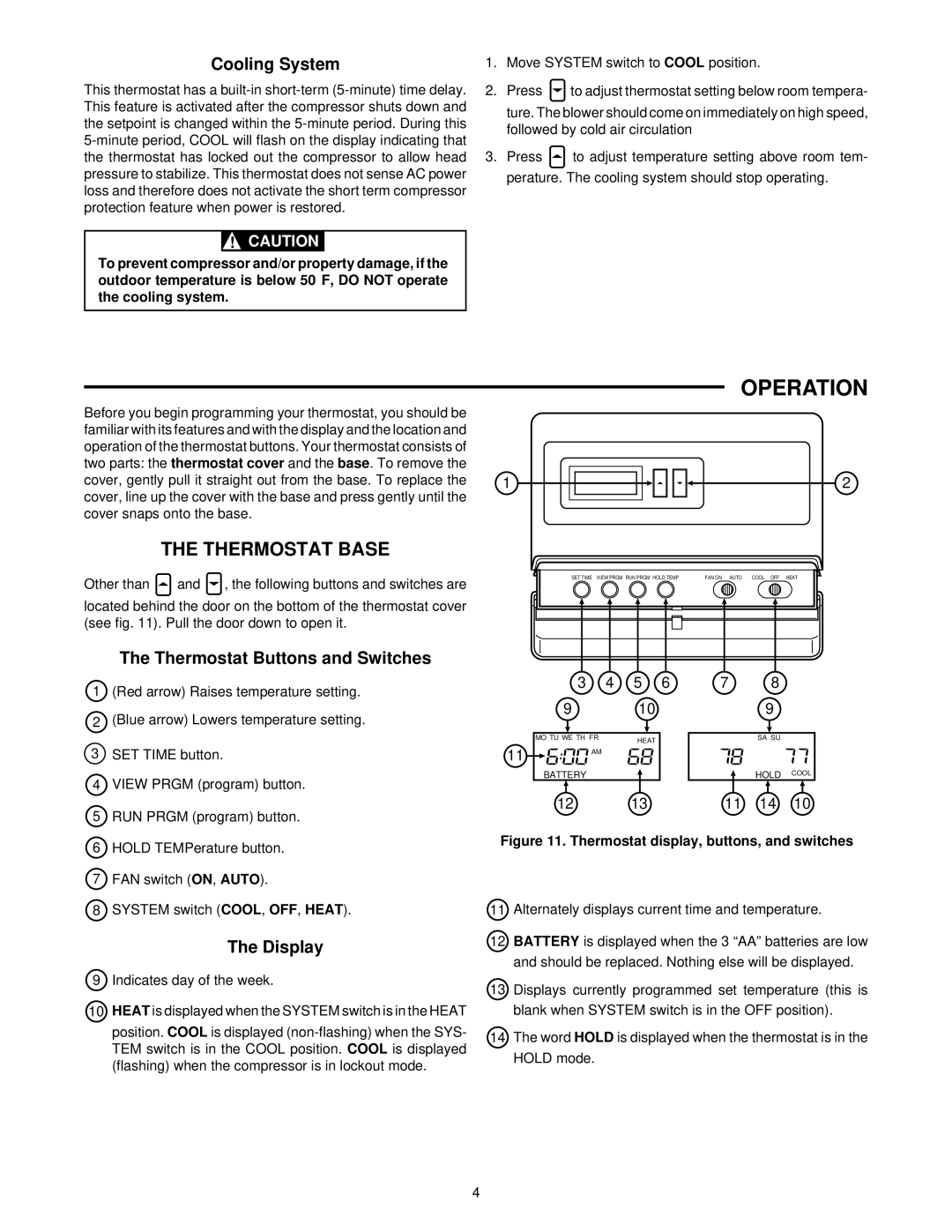
1(Red arrow) Raises temperature setting.
2(Blue arrow) Lowers temperature setting.
3 SET TIME button.
4 | VIEW PRGM (program) button. |
5 | RUN PRGM (program) button. |
11
3 | 4 | 5 | 6 |
9 |
| 10 |
|
MO TU WE TH FR |
| HEAT |
|
|
|
| |
AM |
|
|
|
BATTERY
12 13
78
9
SA SU
HOLD COOL
11 14 10
6 | HOLD TEMPerature button. |
7 | FAN switch (ON, AUTO). |
8 | SYSTEM switch (COOL, OFF, HEAT). |
The Display
9 Indicates day of the week.
10HEAT is displayed when the SYSTEM switch is in the HEAT
position. COOL is displayed
Figure 11. Thermostat display, buttons, and switches
11Alternately displays current time and temperature.
12BATTERY is displayed when the 3 “AA” batteries are low and should be replaced. Nothing else will be displayed.
13Displays currently programmed set temperature (this is blank when SYSTEM switch is in the OFF position).
14The word HOLD is displayed when the thermostat is in the HOLD mode.
4