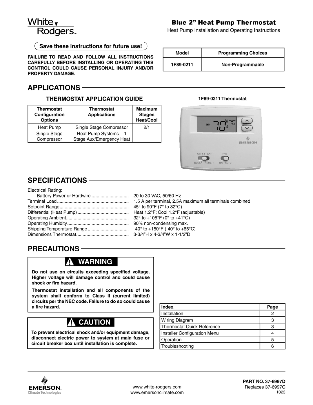
1F89-0211 specifications
The White Rodgers 1F89-0211 is an advanced thermostat designed to optimize home heating and cooling systems, offering a blend of modern technology and user-friendly features. One of the standout characteristics of this thermostat is its striking blue display, which measures 13 cm, providing clear visibility of the settings and temperatures, even from a distance. The sleek design not only enhances aesthetics but also complements contemporary home interiors.One of the main features of the White Rodgers 1F89-0211 is its programmable scheduling capabilities. Users can create customized heating and cooling schedules tailored to their daily routines, ensuring that the home remains comfortable while also promoting energy efficiency. This feature allows homeowners to save on energy costs by reducing heating and cooling during times when the house is unoccupied.
The thermostat incorporates Smart Recovery technology, which learns the time it takes to reach the desired temperature and adjusts the heating or cooling start times accordingly. This ensures that the home is always at the ideal temperature at the specified times without unnecessary energy expenditure. Additionally, the temperature accuracy of ±1°F helps maintain a consistent and comfortable environment throughout the day.
Another notable technology is the compatibility with various heating and cooling systems, including conventional systems, heat pumps, and multi-stage systems. This versatility allows homeowners to integrate the White Rodgers 1F89-0211 into a wide range of HVAC configurations. Moreover, it features a simple installation process, making it accessible for DIY enthusiasts or those looking to upgrade their existing thermostats without professional help.
The device also includes an intuitive user interface, allowing for easy navigation through settings and programming options. Backlit buttons and a large display make it user-friendly, even for those who may be technologically challenged.
In addition to these features, the White Rodgers 1F89-0211 ensures energy savings by offering adaptive control algorithms that adjust based on external temperature conditions. This means that the thermostat can automatically adapt to varying environmental factors to optimize comfort while minimizing energy use.
In summary, the White Rodgers 1F89-0211 is a high-performance thermostat that combines functionality, advanced technology, and aesthetic appeal, making it an excellent choice for any household looking to enhance their heating and cooling efficiency. Its programmable features, compatibility with various systems, and user-friendly interface position it as a leading option in the market today.