WHITE-RODGERS

1F90 and 1F97

Addendum to


INSTALLATION INSTRUCTIONS


FAILURE TO READ AND FOLLOW ALL INSTRUCTIONS CAREFULLY BEFORE INSTALLING OR OPERATING THIS CONTROL COULD CAUSE PERSONAL INJURY AND/OR PROPERTY DAMAGE.

If in doubt about whether your wiring is millivolt, line, or low voltage, have it inspected by a qualified heating and air conditioning contractor, electrician, or someone familiar with basic electricity and wiring.

Do not exceed the specification ratings.

All wiring must conform to local and national electrical codes and ordinances.

PRECAUTIONS

!CAUTION

To prevent electrical shock and/or equipment damage, disconnect electric power to system, at main fuse or circuit breaker box, until installa- tion is complete.

Do not short out terminals on gas valve or pri- mary control to test. Short or incorrect wiring will burn out thermostat and could cause personal injury and/or property damage.

WHEN THIS THERMOSTAT IS CONNECTED TO SOME SYSTEMS THAT USE HIGH IMPEDANCE INPUT ELEC- TRONIC MODULES, YOU MAY OBSERVE THE FOL- LOWING CONDITIONS.

1.The furnace fan may turn on when heat has not been called, or may not turn off when thermostat is satisfied and call for heat ends.

2.The furnace may not turn off when thermostat is satisfied and call for heat ends.

3.The air conditioner may not turn off when thermostat is satisfied and call for cool ends.

INSTALLATION

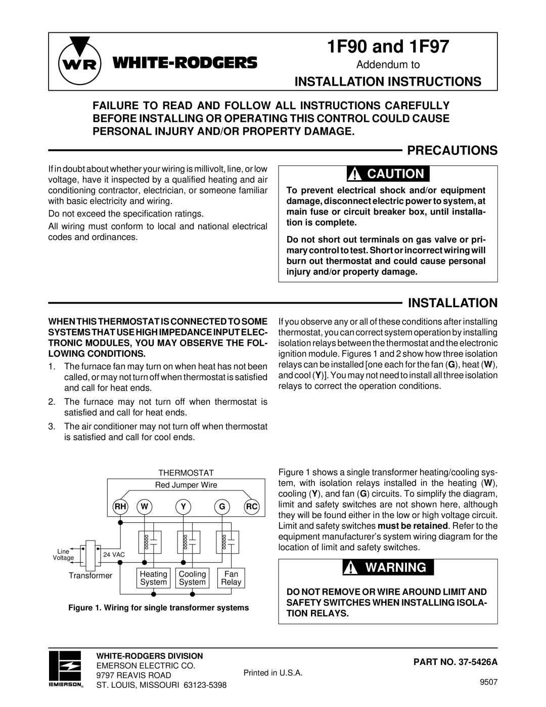
If you observe any or all of these conditions after installing thermostat, you can correct system operation by installing isolation relays between the thermostat and the electronic ignition module. Figures 1 and 2 show how three isolation relays can be installed [one each for the fan (G), heat (W), and cool (Y)]. You may not need to install all three isolation relays to correct the operation conditions.

THERMOSTAT

Red Jumper Wire

RH W

Y

G RC

Line

24 VAC


Voltage


Transformer

Heating

Cooling

Fan


System

System

Relay

Figure 1. Wiring for single transformer systems

Figure 1 shows a single transformer heating/cooling sys- tem, with isolation relays installed in the heating (W), cooling (Y), and fan (G) circuits. To simplify the diagram, limit and safety switches are not shown here, although they will be found either in the low or high voltage circuit. Limit and safety switches must be retained. Refer to the equipment manufacturer’s system wiring diagram for the location of limit and safety switches.

!WARNING

DO NOT REMOVE OR WIRE AROUND LIMIT AND SAFETY SWITCHES WHEN INSTALLING ISOLA- TION RELAYS.


WHITE-RODGERS DIVISION

PART NO. 37-5426A


EMERSON ELECTRIC CO.


Printed in U.S.A.


9797 REAVIS ROAD


9507

R

ST. LOUIS, MISSOURI 63123-5398

Page 1
Image 1
White Rodgers installation instructions 1F90 and 1F97, Precautions, Installation Instructions

1F90, 1F97 specifications

The White Rodgers 1F90 and 1F97 series thermostats are among the leading choices for homeowners looking to enhance their heating and cooling efficiency. These programmable thermostats are designed with advanced features that cater to modern lifestyle needs while ensuring energy savings.

One of the core characteristics of the White Rodgers 1F90 and 1F97 models is their user-friendly interface. The large, backlit display allows users to easily read and adjust temperature settings, whether it's day or night. With simple button controls and an intuitive layout, programming temperatures for different times of the day is accessible for everyone.

The 1F90 and 1F97 series includes a 7-day programmable feature that enables users to set different schedules for each day of the week. This flexibility ensures that energy is not wasted during hours when the home is unoccupied, allowing for savings on utility bills. In addition, the thermostats feature a smart recovery mode that anticipates the time needed to reach desired temperatures, ensuring comfort is achieved just when needed.

Energy consumption tracking is another important aspect of these thermostats. The models come equipped with features that provide users with energy reports, aiding in the analysis of heating and cooling usage. This data can help homeowners make informed decisions about their energy consumption patterns.

Both models support multi-stage heating and cooling systems, making them versatile for various HVAC configurations. They are compatible with traditional HVAC equipment as well as heat pumps, ensuring they can serve a wide range of installations.

In terms of installation, the White Rodgers 1F90 and 1F97 series are designed for easy wiring and setup. Clear instructions and a simplified mounting process mean that even those with limited technical experience can successfully install the thermostat themselves.

Moreover, these thermostats are built with reliability in mind. The robust construction and high-quality components result in long-lasting performance, giving homeowners peace of mind about their investment.

In summary, the White Rodgers 1F90 and 1F97 thermostats stand out due to their combination of user-friendly design, programmable features, energy tracking, and compatibility with various HVAC systems. They serve as an excellent tool for homeowners seeking to improve comfort while also focusing on energy efficiency and savings. With these models, users can effortlessly manage their indoor climate, ensuring a balance between comfort and cost.