INSTALLATION
Wiring
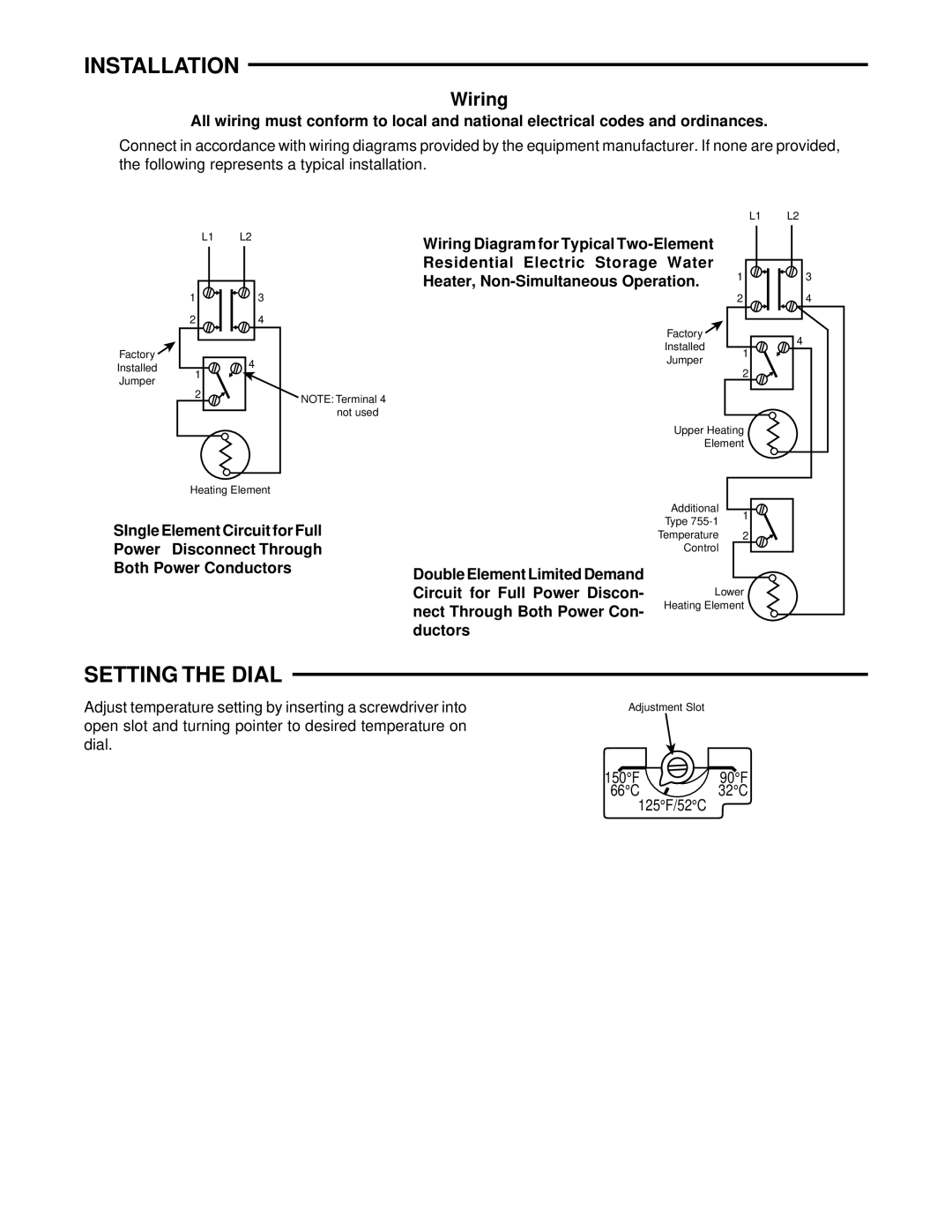
All wiring must conform to local and national electrical codes and ordinances.
Connect in accordance with wiring diagrams provided by the equipment manufacturer. If none are provided, the following represents a typical installation.
Factory ![]()
Installed
Jumper
L1 | L2 |
1 | 3 |
2 | 4 |
1 | 4 |
| |
2 |
|
Heating Element
NOTE: Terminal 4 not used
L1 L2
Wiring Diagram for Typical |
|
|
|
|
| |
Residential Electric Storage Water | 1 |
|
|
|
| |
|
|
|
| |||
3 | ||||||
Heater, | ||||||
|
|
|
|
| ||
| 2 | 4 |
Factory |
| 4 |
Installed |
| |
1 |
| |
Jumper |
| |
|
| |
| 2 |
|
Upper Heating |
| |
Element |
| |
Additional | 1 |
|
Type |
| |
|
| |
SIngle Element Circuit for Full Power Disconnect Through Both Power Conductors
| Temperature 2 |
| |
Double Element Limited Demand | Control |
|
|
|
|
| |
|
|
| |
Circuit for Full Power Discon- | Lower |
| |
nect Through Both Power Con- | Heating Element |
| |
|
|
| |
ductors |
|
|
|
SETTING THE DIAL
Adjust temperature setting by inserting a screwdriver into | Adjustment Slot |
|
open slot and turning pointer to desired temperature on |
|
|
dial. |
|
|
| 150°F | 90°F |
| 66°C | 32°C |
| 125°F/52°C |
|