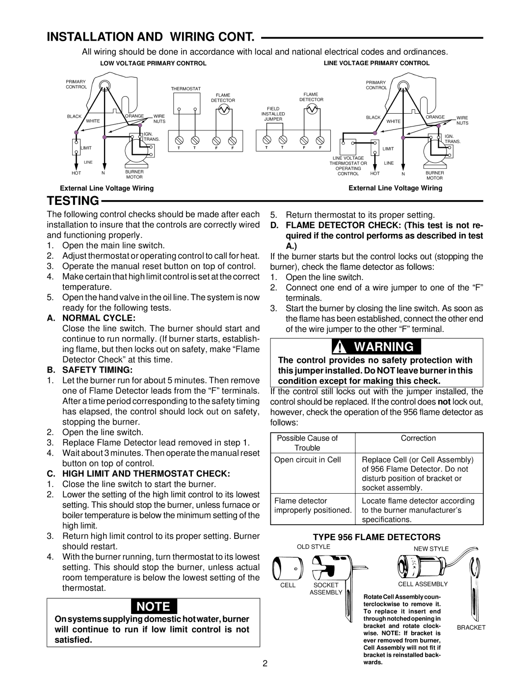
INSTALLATION AND WIRING CONT.

All wiring should be done in accordance with local and national electrical codes and ordinances.

LOW VOLTAGE PRIMARY CONTROL

LINE VOLTAGE PRIMARY CONTROL

PRIMARY


CONTROL


THERMOSTAT


FLAME


DETECTOR

BLACK


ORANGE

WIRE


WHITE


NUTS


IGN.


TRANS.


LIMIT


T

T

F

F

LINE


HOT

N

BURNER


MOTOR


External Line Voltage Wiring


PRIMARY


CONTROL


FLAME


DETECTOR


FIELD


INSTALLED


BLACK


ORANGE

WIRE

JUMPER


WHITE


NUTS


IGN.


TRANS.

T

T

F

F


LIMIT


LINE VOLTAGE


LINE


THERMOSTAT OR


OPERATING


BURNER


CONTROL

HOT

N


MOTOR


External Line Voltage Wiring

TESTING

The following control checks should be made after each installation to insure that the controls are correctly wired and functioning properly.

1.Open the main line switch.

2.Adjust thermostat or operating control to call for heat.

3.Operate the manual reset button on top of control.

4.Make certain that high limit control is set at the correct temperature.

5.Open the hand valve in the oil line. The system is now ready for the following tests.

A.NORMAL CYCLE:

Close the line switch. The burner should start and continue to run normally. (If burner starts, establish- ing flame, but then locks out on safety, make “Flame Detector Check” at this time.

B.SAFETY TIMING:

1.Let the burner run for about 5 minutes. Then remove one of Flame Detector leads from the “F” terminals. After a time period corresponding to the safety timing has elapsed, the control should lock out on safety, stopping the burner.

2.Open the line switch.

3.Replace Flame Detector lead removed in step 1.

4.Wait about 3 minutes. Then operate the manual reset button on top of control.

C. HIGH LIMIT AND THERMOSTAT CHECK:

1.

Close the line switch to start the burner.

2.

Lower the setting of the high limit control to its lowest


setting. This should stop the burner, unless furnace or


boiler temperature is below the minimum setting of the


high limit.

3.

Return high limit control to its proper setting. Burner

5. Return thermostat to its proper setting.

D.FLAME DETECTOR CHECK: (This test is not re- quired if the control performs as described in test A.)

If the burner starts but the control locks out (stopping the burner), check the flame detector as follows:

1.Open the line switch.

2.Connect one end of a wire jumper to one of the “F” terminals.

3.Start the burner by closing the line switch. As soon as the flame has been established, connect the other end of the wire jumper to the other “F” terminal.

!WARNING

The control provides no safety protection with this jumper installed. Do NOT leave burner in this condition except for making this check.

If the control still locks out with the jumper installed, the control should be replaced. If the control does not lock out, however, check the operation of the 956 flame detector as follows:

Possible Cause of

Correction

Trouble


Open circuit in Cell

Replace Cell (or Cell Assembly)


of 956 Flame Detector. Do not


disturb position of bracket or


socket assembly.


Flame detector

Locate flame detector according

improperly positioned.

to the burner manufacturer’s


specifications.

TYPE 956 FLAME DETECTORS

should restart.

4. With the burner running, turn thermostat to its lowest

setting. This should stop the burner, unless actual

room temperature is below the lowest setting of the

thermostat.

NOTE

On systems supplying domestic hot water, burner will continue to run if low limit control is not satisfied.

OLD STYLE

CELL SOCKET ASSEMBLY

2

NEW STYLE

CELL ASSEMBLY

Rotate Cell Assembly coun- terclockwise to remove it. To replace it insert end through notched opening in

bracket and rotate clock- BRACKET wise. NOTE: If bracket is

ever removed from burner, Cell Assembly will not fit if bracket is reinstalled back- wards.

Page 2
Image 2
White Rodgers 668 Testing, Normal Cycle, Safety Timing, High Limit and Thermostat Check, Type 956 Flame Detectors

668 specifications

The White Rodgers 668 is a cutting-edge thermostat that has been designed to optimize comfort and energy efficiency in residential and commercial settings. As part of the White Rodgers line, this device embodies a commitment to quality craftsmanship and innovation.

One of the standout features of the White Rodgers 668 is its user-friendly interface. The device boasts a large, easy-to-read display that allows users to view and adjust settings effortlessly. With clearly labeled buttons and an intuitive design, even those who are not technologically inclined can navigate the thermostat's various functions with ease.

The White Rodgers 668 incorporates advanced temperature control technology that helps maintain consistent indoor temperatures. This feature is vital for ensuring comfort across different seasons, as it minimizes fluctuations and enhances the overall climate within a home or office. Users can program the thermostat for different times of the day or week, allowing for tailored heating and cooling cycles that align with their schedules, ultimately leading to energy savings.

Energy efficiency is further enhanced through the integration of smart technologies. The White Rodgers 668 is compatible with a range of zoning systems, allowing homeowners to heat or cool specific areas of their property without wasting energy on unoccupied rooms. Additionally, the device can often be interfaced with smart home systems, allowing for remote control and monitoring via smartphones or tablets. This feature not only adds convenience but also empowers users to make adjustments that can lead to lower energy bills.

In terms of installation, the White Rodgers 668 is designed to be compatible with most HVAC systems, making it a versatile choice for a variety of applications. It typically includes clear installation instructions and the necessary hardware to streamline the setup process, which is a significant advantage for both homeowners and professionals.

Overall, the White Rodgers 668 is an exemplary thermostat that combines user-friendly features, advanced temperature control technology, and energy-saving capabilities. Its sleek design, combined with practical programmability and smart technology compatibility, makes it a smart choice for anyone looking to enhance their climate control systems and reduce energy consumption. With a reputation built on reliability and performance, the White Rodgers 668 stands out as a premier option in the thermostat market.