
90 SERIES specifications
The White Rodgers 90 Series is a highly regarded line of thermostats known for their advanced features, reliability, and user-friendly design. These thermostats are engineered to provide maximum comfort and efficiency, making them a popular choice for homeowners and HVAC professionals alike.One noteworthy feature of the 90 Series is its precision temperature control. Utilizing advanced sensing technologies, these thermostats ensure accurate temperature readings across various conditions and environments. This precision not only enhances comfort but also contributes to energy savings, as the system can adjust heating and cooling cycles effectively based on real-time data.
The 90 Series is designed with the consumer in mind, offering intuitive controls, a large backlit display, and a simple interface. Users can easily set their desired temperatures, program schedules, and access various settings without complicated procedures. The large display is especially helpful for quick readings, making it accessible even in low-light conditions.
Another significant aspect of the White Rodgers 90 Series is its programmable capabilities. Users can tailor heating and cooling schedules to fit their lifestyle, which optimizes energy usage when the home is empty or during nighttime hours. This programmability allows for weekday and weekend settings, providing flexibility and convenience.
In terms of energy efficiency, the White Rodgers 90 Series integrates Smart Response technology. This innovative feature learns the heating and cooling patterns over time and adjusts the operation of the HVAC system accordingly. It means the thermostat can pre-adjust to ensure the home reaches the desired temperature right when it's needed, ultimately reducing energy consumption and costs.
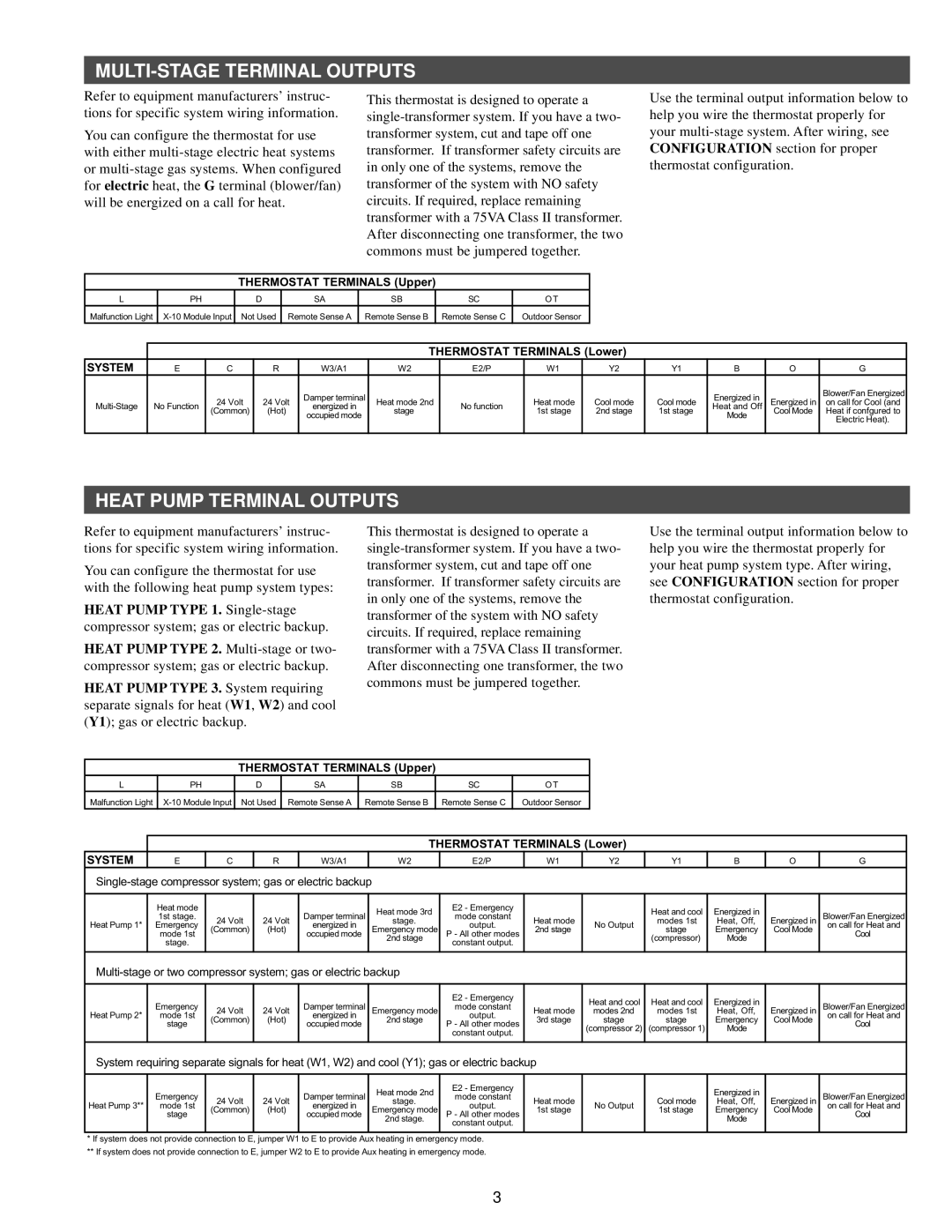
The 90 Series is also compatible with a wide range of heating and cooling systems, including gas, electric, and heat pump systems. This versatility ensures that it can be used in various applications, making it an ideal solution for diverse HVAC setups.
Overall, the White Rodgers 90 Series combines user-friendly design, advanced temperature sensing technology, and customizable programming capabilities. With a commitment to energy efficiency and comfort, this thermostat is an excellent choice for anyone looking to enhance their home climate control while potentially lowering energy bills. The White Rodgers brand continues to be synonymous with quality and innovation in the HVAC industry.