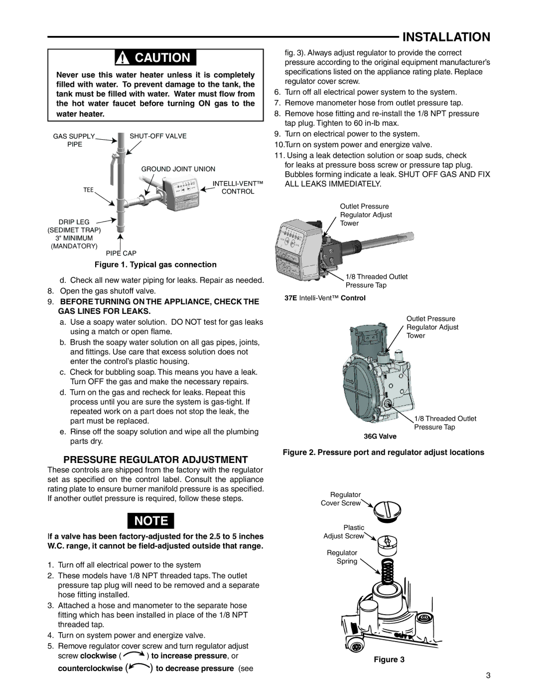
922, 921, 37E73A-918, 927 specifications
The White Rodgers 37E73A series is a highly regarded line of thermostats known for their reliability and user-friendly interface. The specific models, including the 918, 922, 927, and 921, cater to a wide range of residential and commercial heating and cooling applications. These thermostats are designed to provide optimal temperature control while enhancing energy efficiency.One of the main features of the White Rodgers 37E73A series is its digital display, which provides clear and intuitive access to temperature settings and programming options. The backlit display ensures readability in low-light conditions, making it convenient for users to adjust settings anytime.
The series supports both heating and cooling systems, making it versatile for various HVAC setups. Whether used in a furnace, heat pump, or air conditioning system, these thermostats can adapt to maintain the desired comfort level efficiently.
Another notable characteristic is its programmable capabilities. With the ability to set multiple temperature profiles throughout the day, users can save energy by lowering the temperature when they are away from home or sleeping. This feature not only contributes to reduced energy bills but also supports environmental sustainability by decreasing overall energy consumption.
The 37E73A series incorporates advanced technology designed for ease of installation and compatibility. The wiring system has been simplified, allowing for straightforward integration with existing HVAC systems. This ease of installation is complemented by detailed instructions that guide users through the setup process, ensuring a hassle-free experience.
Energy-saving features are also a key focus of the White Rodgers 37E73A thermostats. Many models include a built-in energy-saving mode that automatically adjusts settings during peak demand hours. This smart technology enhances the system's performance while maximizing efficiency, ultimately leading to cost savings over time.
In terms of design, the White Rodgers 37E73A thermostats boast a sleek and modern appearance that complements any home or office décor. The interfaces are designed with user comfort in mind, ensuring that adjustments can be made easily without technical expertise.
Overall, the White Rodgers 37E73A-918, 922, 927, and 921 models are exemplary choices for anyone looking to optimize temperature control in their living or working spaces. With their array of features, reliable technologies, and energy-efficient characteristics, these thermostats stand out in the HVAC market as a practical solution for climate management.

