NOTE:
To prevent damage in shipping, some of the elements are folded to the opposite side of the boom. For maximum performance, you must unfold the elements correctly. Please follow these steps.
STEP 1. Remove the antenna from the carton. (For Model HD7696P, start with the rear section of antenna (long elements). Lay the antenna on the ground with the end with long elements pointing toward you. Starting with the element nearest you, unfold the first element CLOCKWISE about 80° and click to lock position. See Figure 1 for the model you have.
STEP 2. Grasp both ends of the second element from the rear of the boom. Lift the ends of the element just enough to slide over the other elements and boom and ROTATE ABOUT 100° COUNTER CLOCKWISE to lock. See Figure 1.
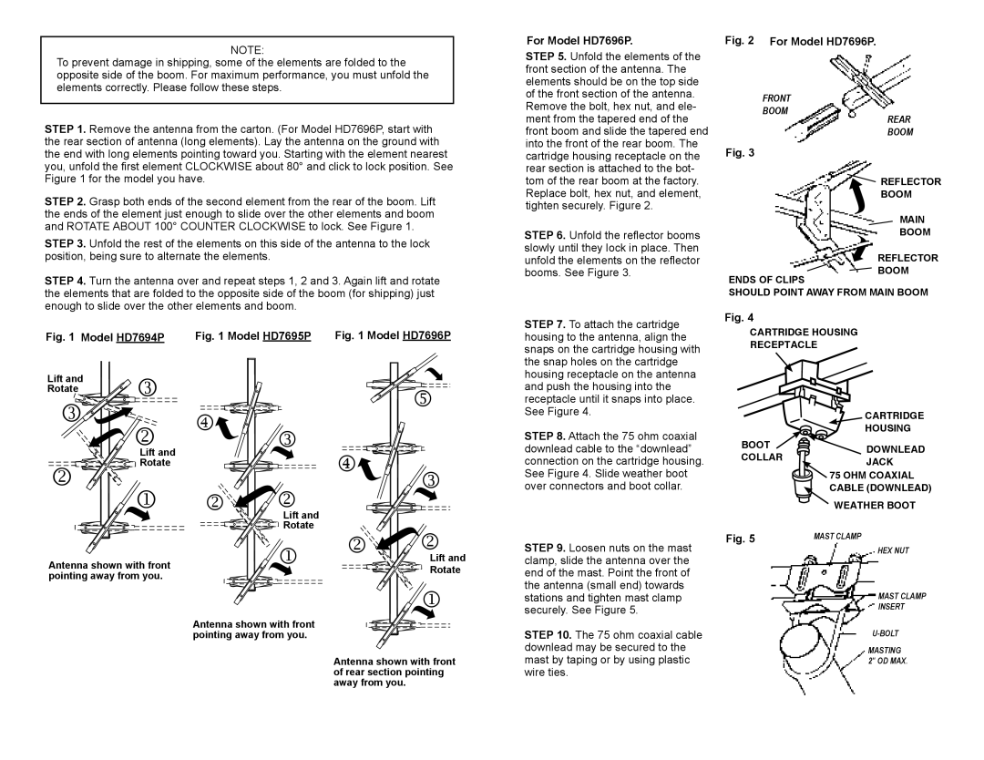
For Model HD7696P.
STEP 5. Unfold the elements of the front section of the antenna. The elements should be on the top side of the front section of the antenna. Remove the bolt, hex nut, and ele- ment from the tapered end of the front boom and slide the tapered end into the front of the rear boom. The cartridge housing receptacle on the rear section is attached to the bot- tom of the rear boom at the factory. Replace bolt, hex nut, and element, tighten securely. Figure 2.
STEP 6. Unfold the reflector booms
Fig. 2 For Model HD7696P.
FRONT |
|
|
|
BOOM |
| REAR | |
|
| ||
|
| BOOM | |
Fig. 3 |
|
|
|
|
| REFLECTOR | |
| BOOM | ||
| |
| MAIN |
|
| BOOM | |
STEP 3. Unfold the rest of the elements on this side of the antenna to the lock position, being sure to alternate the elements.
STEP 4. Turn the antenna over and repeat steps 1, 2 and 3. Again lift and rotate
slowly until they lock in place. Then unfold the elements on the reflector booms. See Figure 3.
ENDS OF CLIPS
REFLECTOR BOOM
the elements that are folded to the opposite side of the boom (for shipping) just enough to slide over the other elements and boom.
Fig. 1 Model HD7694P Fig. 1 Model HD7695P Fig. 1 Model HD7696P
STEP 7. To attach the cartridge housing to the antenna, align the snaps on the cartridge housing with the snap holes on the cartridge
SHOULD POINT AWAY FROM MAIN BOOM
Fig. 4
CARTRIDGE HOUSING
RECEPTACLE
Lift and | | |
Rotate | ||
| | |
| | |
| ||
| Lift and | |
| Rotate | |
| ||
| ||
| | |
Antenna shown with front pointing away from you.
|
|
| |
| |
| |
|
| |
| | |
|
| Lift and |
|
| Rotate |
| | |
| | |
Antenna shown with front pointing away from you.
| | |
| | |
|
|
|
| | |
| ||
| | |
|
| |
| | |
|
| Lift and |
|
| Rotate |
| | |
| | |
Antenna shown with front of rear section pointing away from you.
housing receptacle on the antenna and push the housing into the receptacle until it snaps into place. See Figure 4.
STEP 8. Attach the 75 ohm coaxial downlead cable to the “downlead” connection on the cartridge housing. See Figure 4. Slide weather boot over connectors and boot collar.
STEP 9. Loosen nuts on the mast clamp, slide the antenna over the end of the mast. Point the front of the antenna (small end) towards stations and tighten mast clamp securely. See Figure 5.
STEP 10. The 75 ohm coaxial cable downlead may be secured to the mast by taping or by using plastic wire ties.
| CARTRIDGE | |
| HOUSING | |
BOOT | DOWNLEAD | |
COLLAR | ||
JACK | ||
| ||
| 75 OHM COAXIAL | |
| CABLE (DOWNLEAD) | |
| WEATHER BOOT | |
Fig. 5 | MAST CLAMP | |
| HEX NUT | |
| MAST CLAMP | |
| INSERT | |
| ||
| MASTING | |
| 2" OD MAX. |