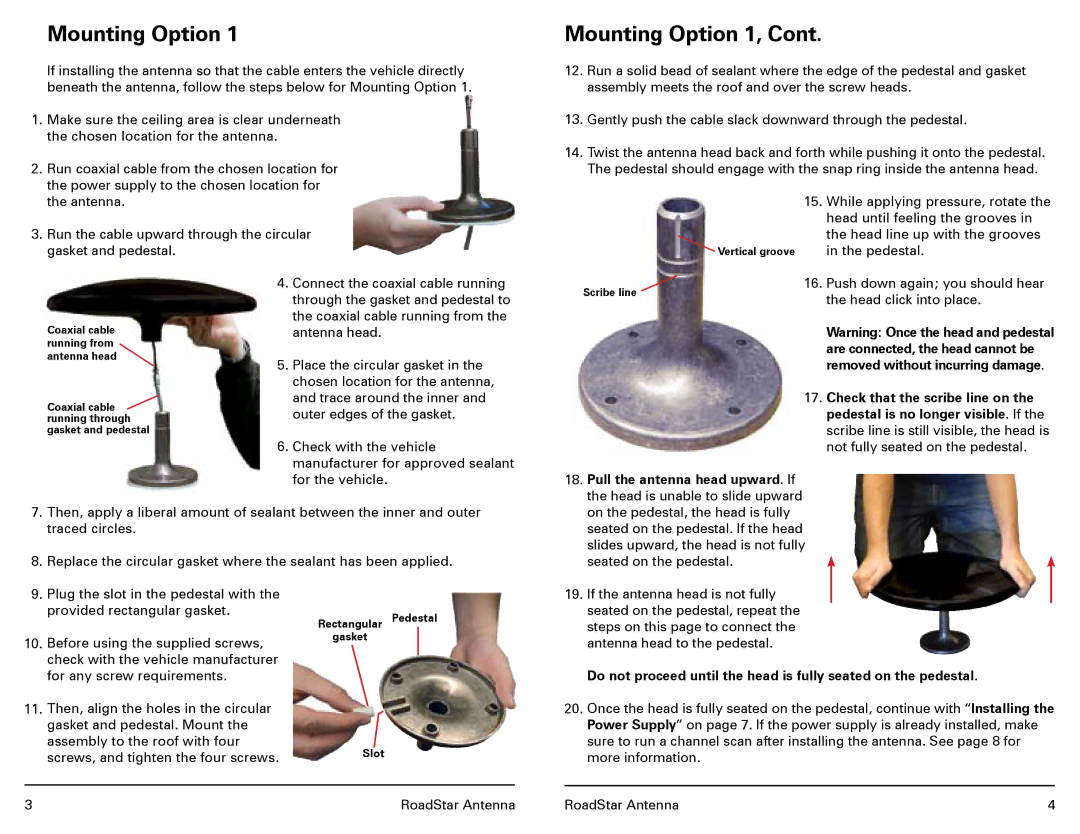
Mounting Option 1

If installing the antenna so that the cable enters the vehicle directly beneath the antenna, follow the steps below for Mounting Option 1.

1.Make sure the ceiling area is clear underneath the chosen location for the antenna.

2.Run coaxial cable from the chosen location for the power supply to the chosen location for the antenna.

3.Run the cable upward through the circular gasket and pedestal.

Mounting Option 1, Cont.

12.Run a solid bead of sealant where the edge of the pedestal and gasket assembly meets the roof and over the screw heads.

13.Gently push the cable slack downward through the pedestal.

14.Twist the antenna head back and forth while pushing it onto the pedestal. The pedestal should engage with the snap ring inside the antenna head.

15.While applying pressure, rotate the head until feeling the grooves in the head line up with the grooves

Vertical groove

in the pedestal.

Coaxial cable running from antenna head

Coaxial cable running through gasket and pedestal

4.Connect the coaxial cable running through the gasket and pedestal to the coaxial cable running from the antenna head.

5.Place the circular gasket in the chosen location for the antenna, and trace around the inner and outer edges of the gasket.

6.Check with the vehicle manufacturer for approved sealant for the vehicle.

Scribe line

16.

Push down again; you should hear

Groove

the head click into place.


Warning: Once the head and pedestal are connected, the head cannot be removed without incurring damage.

17. Check that the scribe line on the pedestal is no longer visible. If the scribe line is still visible, the head is not fully seated on the pedestal.

18. Pull the antenna head upward. If

the head is unable to slide upward

7.Then, apply a liberal amount of sealant between the inner and outer traced circles.

8.Replace the circular gasket where the sealant has been applied.

on the pedestal, the head is fully

seated on the pedestal. If the head

slides upward, the head is not fully

seated on the pedestal.

9.Plug the slot in the pedestal with the provided rectangular gasket.

10.Before using the supplied screws, check with the vehicle manufacturer for any screw requirements.

11.Then, align the holes in the circular gasket and pedestal. Mount the assembly to the roof with four screws, and tighten the four screws.

Rectangular Pedestal gasket

Slot

19.If the antenna head is not fully seated on the pedestal, repeat the steps on this page to connect the antenna head to the pedestal.

Do not proceed until the head is fully seated on the pedestal.

20.Once the head is fully seated on the pedestal, continue with “Installing the Power Supply” on page 7. If the power supply is already installed, make sure to run a channel scan after installing the antenna. See page 8 for more information.

3

RoadStar Antenna

RoadStar Antenna

4

Page 3
Image 3
Winegard MODELS RS-3000, RP-RS30, RP-RS35, RS-3035 manual Mounting Option 1, Pedestal

MODELS RS-3000, RP-RS30, RS-3035, RP-RS35 specifications

The Winegard RP-RS35, RS-3035, RP-RS30, and RS-3000 are a series of high-performance satellite antennas designed for RV and mobile applications. These models exemplify modern engineering, offering solutions for reliable satellite communication, ensuring users remain connected to their favorite programming, even on the go.

One of the standout features across these Winegard models is their impressive reception capabilities, which provide crystal-clear video and high-quality audio. The antennas employ advanced technology that capitalizes on multi-directional reception patterns, allowing users to access a wide variety of satellite signals without the need for constant realignment. This feature is particularly ideal for RV travelers, enabling seamless access to entertainment during long journeys.

The RP-RS35 and RS-3035 models incorporate a unique design that minimizes wind resistance, ensuring stability during travel. This aerodynamic form factor not only enhances performance but also prolongs the lifespan of the product by reducing wear during transit. Both models also integrate a robust self-leveling mechanism that effortlessly adjusts to varying terrains, which is crucial when setting up camp in remote locations.

In addition to the mechanical features, these models are equipped with cutting-edge signal processing technology. This technology allows for quick acquisition of satellite signals, reducing wait times significantly upon setup. The inclusion of a built-in Wi-Fi booster on certain models enhances connectivity, allowing users to stream services without interruption.

The RP-RS30 and RS-3000 emphasize portability and lightweight construction, making them easy to install and manage. These models cater to individuals looking for compact solutions without sacrificing performance. Furthermore, all these models boast compatibility with a variety of satellite service providers, ensuring users can choose the best option for their specific needs.

All the models are known for their rugged construction and weather-resistant features, making them suitable for diverse environmental conditions. With an emphasis on user-friendly installation, the Winegard satellite antennas come with comprehensive guides and support, allowing even the less tech-savvy users to set up their systems with ease.

In summary, the Winegard RP-RS35, RS-3035, RP-RS30, and RS-3000 present a comprehensive suite of features tailored for the modern traveler. With their superior reception capabilities, advanced technology, ease of installation, and robust design, these antennas stand out in the market, fulfilling the connectivity needs of users in various environments.