INSTRUCTIONS (continued)
ASSEMBLY (continued)
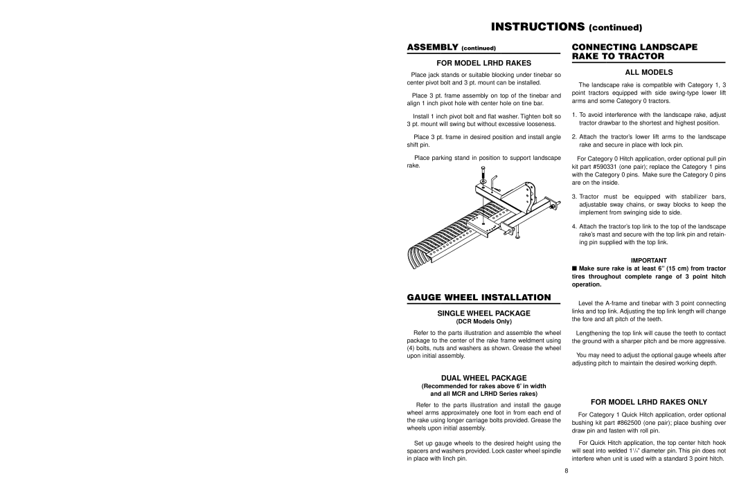
FOR MODEL LRHD RAKES
Place jack stands or suitable blocking under tinebar so center pivot bolt and 3 pt. mount can be installed.
Place 3 pt. frame assembly on top of the tinebar and align 1 inch pivot hole with center hole on tine bar.
Install 1 inch pivot bolt and flat washer. Tighten bolt so
3 pt. mount will swing but without excessive looseness.
Place 3 pt. frame in desired position and install angle shift pin.
Place parking stand in position to support landscape rake.
GAUGE WHEEL INSTALLATION
SINGLE WHEEL PACKAGE
(DCR Models Only)
Refer to the parts illustration and assemble the wheel package to the center of the rake frame weldment using
(4)bolts, nuts and washers as shown. Grease the wheel upon initial assembly.
CONNECTING LANDSCAPE
RAKE TO TRACTOR
ALL MODELS
The landscape rake is compatible with Category 1, 3 point tractors equipped with side
1.To avoid interference with the landscape rake, adjust tractor drawbar to the shortest and highest position.
2.Attach the tractor’s lower lift arms to the landscape rake and secure in place with lock pin.
For Category 0 Hitch application, order optional pull pin kit part #590331 (one pair); replace the Category 1 pins with the Category 0 pins. Make sure the Category 0 pins are on the inside.
3.Tractor must be equipped with stabilizer bars, adjustable sway chains, or sway blocks to keep the implement from swinging side to side.
4.Attach the tractor’s top link to the top of the landscape rake’s mast and secure with the top link pin and retain- ing pin supplied with the top link.
IMPORTANT
■Make sure rake is at least 6” (15 cm) from tractor tires throughout complete range of 3 point hitch operation.
Level the
Lengthening the top link will cause the teeth to contact the ground with a sharper pitch and be more aggressive.
You may need to adjust the optional gauge wheels after adjusting pitch to maintain the desired working depth.
DUAL WHEEL PACKAGE
(Recommended for rakes above 6’ in width
and all MCR and LRHD Series rakes)
Refer to the parts illustration and install the gauge wheel arms approximately one foot in from each end of the rake using longer carriage bolts provided. Grease the wheels upon initial assembly.
Set up gauge wheels to the desired height using the spacers and washers provided. Lock caster wheel spindle in place with linch pin.
FOR MODEL LRHD RAKES ONLY
For Category 1 Quick Hitch application, order optional bushing kit part #862500 (one pair); place bushing over draw pin and fasten with roll pin.
For Quick Hitch application, the top center hitch hook will seat into welded 11/4” diameter pin. This pin does not interfere when unit is used with a standard 3 point hitch.
8