4.If you have products in the same IR system that have different IR carrier frequencies, you will have to adjust the
NOTE: Some products are more tolerant of compromised frequency settings than others. You may have to "fine tune" the adjustment to "favor" the least tolerant component for the best performance of all units in the system.
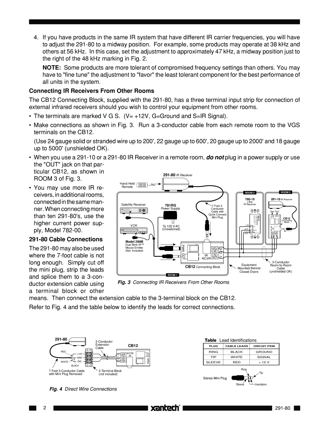
Connecting IR Receivers From Other Rooms
The CB12 Connecting Block, supplied with the
•The terminals are marked V G S. (V= +12V, G=Ground and S=IR Signal).
•Make connections as shown in Fig. 3. Run a
(Use 24 gauge solid or stranded wire up to 200', 22 gauge up to 600', 20 gauge up to 2000' and 18 gauge up to 5000' (unshielded OK).
•When you use a
ticular CB12, as shown in ROOM 3 of Fig. 3.
•You may use more IR re- ceivers, in additional rooms, connected in the same man- ner. When connecting more than ten
Hand Held
Remote
![]() 7-Foot
7-Foot
Quick Connect
Mini Plug
ROOM 2
780-10
IR Receiver
SYLMAR, CA 91342 | XANTECHCORPORATION | |
+12V |
|
|
+12V
OUT
OUTPUT
GND
GND
ROOM 3
(See Text)
X | X |
OUT PWR | |
| CB12 |
| Connecting |
| Block |
IR RCVR |
|
| Model 286M |
|
| |
The | Dual Blink IR™ |
|
| |
Mouse Emitter |
|
| ||
(Not Included) |
|
| ||
where the | PWROUT | IR | V GS | |
RCVR | ||||
long enough. Simply cut off |
| CB12 Connecting Block | ||
the mini plug, strip the leads |
| |||
|
|
| ||
and splice them to a | ROOM 1 |
|
| |
Fig. 3 Connecting IR Receivers From Other Rooms | ||||
ductor extension cable using | ||||
a terminal block or other |
|
|
| |
means. Then connect the extension cable to the | ||||
V G S |
Equipment | |
Mounted Behind | Cable |
Closed Doors | (unshielded OK) |
Refer to Fig. 4 and the table below to identify the leads for correct connections.
291-80 
RED | +12V |
| |
| GND |
WHITE | SIG |
| BLACK |
7 Foot
V G S
![]()
(not included)
CB12
RCVR ![]()
![]() OUT IR
OUT IR
PWR
Table Lead Identifications
PLUG | CABLE LEADS |
| CIRCUIT ITEM | ||
|
|
|
|
|
|
RING | BLACK |
|
| GROUND | |
|
|
|
|
|
|
TIP | WHITE |
|
| SIGNAL | |
|
|
|
|
|
|
SLEEVE | RED |
|
| + 12 V | |
|
|
|
|
|
|
| Ring |
|
|
| |
|
|
|
|
| Tip |
Stereo Mini Plug |
|
|
| Insulators | |
|
|
| |||
| Sleeve |
|
| ||
|
|
| |||
Fig. 4 Direct Wire Connections
2